Continue to Site

Eng-Tips is the largest engineering community on the Internet

Intelligent Work Forums for Engineering Professionals

  • Congratulations KootK on being selected by the Eng-Tips community for having the most helpful posts in the forums last week. Way to Go!

Minimum axial design actions on connections 1

Status
Not open for further replies.

kauri

Structural
Aug 13, 2018
36
Hi, from my code NZS3404 for steel design, there is the requirement for minimum design actions acting on steel connections: "Connections at the end of tension or compression members - a force of 0.3 times the member design capacity". I'm looking at designing some epoxy bolts for small columns which primarily take gravity loads, but under uplift may experience tension. So this requirement to design the columns for 30% member tension capacity will kill my design.

Eg, I have 125SHS column sized for gravity loads and EQ lateral deflections, epoxy bolted to concrete. Under uplift it takes 20kN tension; under 30% member tensile capacity I need to size it for 400kN tension. How the f**k do I design my epoxy bolts for 400kN tension?? xD I must be missing something here.
 
Replies continue below

Recommended for you

Agent666 said:
The unfortunate thing is that make zero sense.

For example say you have a column with 20kN load in tension and compression and a 300kN compression member capacity and a 3000kN section tension capacity.

Then for tension using that logic you're designing for 30% of the section tension capacity (1000kN). But for compression you're designing for 30% of a potentially much smaller compression member buckling load (100kN). That makes no sense at all.
I agree with it making no sense. Hence me vigorously scratching my head at both interpretations. It makes no sense to interpret the tension connection capacity in the context of this minimum size of member context as in the words of jrbaus SIX years ago.

jrbaus said:
if you read the preface for the 2012 commentary you will see it mentions to delete the wording "for the minimum size of member" of clause 9.1.4.

It was changed to reflect the intentions of the original panel I believe (I found a publication stating this but cant for the life of me remember where). It made little sense to me in its original form to design for 30% of the member capacity for a member being utilised at 100%!

In its current form, I treat this clause as a robustness requirement only. Sometimes we provide members heavier than required to make allowances for corrosion, impact, local effects etc and therefore it is foreseeable that minimum design actions may govern. In saying that, I would expect minimum design actions to govern connections such as splices in beams etc. much more frequently than splices in tension members since tension members are generally uniformly loaded and as such the position of the splice will not significantly impact the design loads as you would expect to be the case for a continuous floor beam or something along these lines.

My treatment of this clause has been as jrbaus has mentioned, a robustness requirement to ensure one doesn't provide excessively small connections on large members. The alternative interpretation had never occurred to me until today because AS4100 doesn't have that detail about minimum size of member. I am still puzzled how one should treat such a clause because I have readily imagine all sorts of minimum size of members that dodge neatly around the code in such a way that they sit on the edge of all the member design capacities and therefore render section (b) meaningless. In case it isn't clear I'm not advocating that my interpretation is the correct one as the NZ wording and the previous AS wording seems to imply something different. I'm mostly just puzzled.

For what it is worth here is the commentary/interpretation from SpaceGass software on this matter (obviously this is just another interpretation and not an authority):
Minimum design actions
In order to ensure that each connection is well proportioned and robust, especially when the analysis design actions are quite low, the code nominates minimum design actions that should be complied with. Normally you would leave this option ticked, however you can turn it off if required.


For what it is worth I have used the minimum design actions for pretty much everything except for the "tension member" as anything but TENSION only members eg tension angles, rod bracing etc. The only time I've found meeting member design actions in anyway onerous is for moment connections. But I've also believe that this is understandable because the indeterminacy of moment frames can potentially mean a connection sees a fair bit more moment than your idealised model may suggest.
 
Human909, yeah I found that reply from jrbaus as well when searching. The phiNc requirements still makes no sense to me, because it is essentially the same thing they were referring to if phiNc is obviously sometimes significantly less than phiNs, and 30% of a smaller capacity arguably doesn't always impart the robustness requirement that was intended by this clause. But that is perhaps not much different than basing the requirement on the minimum member size issue as well....

On the software front I checked in Limcon as well, and they use phiNc for compression, phiMs for flexure and phiNt for tension for applying the percentages to.


steveh49 said:
Edit: Pondering more, it is conceivable that connexion academix who live in the 1m^3 box around member intersections wouldn't be aware of the distinction between section and member capacity definitions in the code, and so not take care in their wording. The members apply load to the connection but are otherwise an irrelevance.
Quite possibly, any of the suggests in this thread are potential interpretations....


I did find this in some SCNZ literature which makes the distinction between member and section capacities for non-seismic and seismic respectively. Which suggests phiNc member capacity would be used for non-seismic, but also implies phiMb vs phiMs as well for non-seismic if you take the argument to the limit... but nowhere have I seen anyhting regarding member capacity = phiMb for flexure, they all seem to be interpreting member design capacity for flexure as phiMs, when this is the section design capacity...
image_zibowl.png


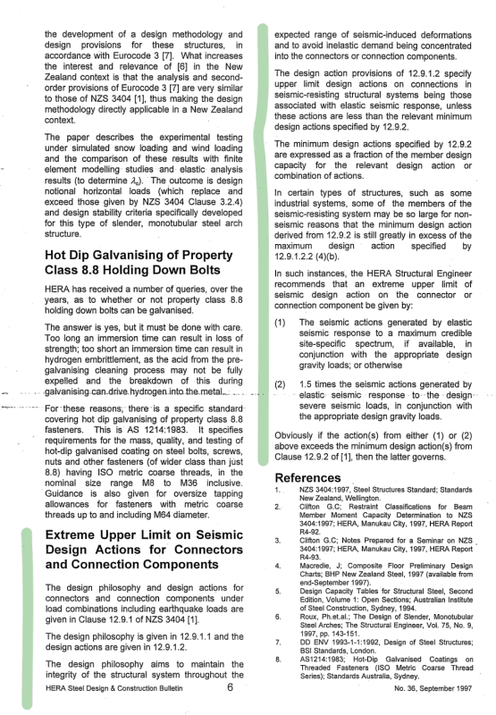
ALso see this advice, for seismic the option is there to take the max MCE actions as an upper limit if the actions are low, but the sections are grossly oversized.
image_qxaeda.png

[from HERA DCB36]

 
We I posted at a pretty late time last night, I actually didn't quite grasp the distinction being made between member capacity and section capacity. But having another look, it is pretty clear that is another aspect of confusion in the whole piece. I've always assume section capacity as that is what has made sense to me but the text quite clear refers to member and not section. Additionally the exact phrase "member design capacity" only appears a small number of times in the AS4100 and only in regard to connections. Where it appears in seismic sections it seems to make perfect sense but it seems out of place in the non seismic connection design minimums. And NZ3404 situation isn't too much different.

[pharaoh] This discussion is almost like a theological discussion about the meaning of the holy texts. While we know they were written by imperfect code writers based on the teachings of the Gods of Engineering, it still can be a source of existential angst in working out what it all really means and whether my understanding of it has been wrong all this time. Oh and thrown into the mix are two branches of only slightly divergent sects of the same religion who have slightly different texts to refer too. Those in lands far away who follow completely different codes must be looking on at this discussion with bemusement. (And of course content in knowing that their Code is the one true Code. [lol] )
 
Status
Not open for further replies.

Part and Inventory Search

Sponsor