Continue to Site

Eng-Tips is the largest engineering community on the Internet

Intelligent Work Forums for Engineering Professionals

  • Congratulations waross on being selected by the Eng-Tips community for having the most helpful posts in the forums last week. Way to Go!

Minimum chilled water bypass loop volume requirement (2-minute) - MultiStack MagLev

Status
Not open for further replies.

Jo-

Mechanical
Oct 10, 2022
2
Hello All,

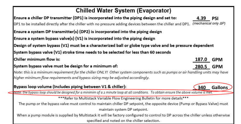
I'm working on a chiller plant replacement project involving the installation of two (2) 180-ton each MultiStack MagLev water cooled chillers (one on standby) that has a designed flowrate of 373gpm thru each chiller. MultiStack has included in their submittal the following requirements (see below) concerning the minimum chilled water flowrates(187gpm) thru the chiller as well as the required minimum (340 Gallons) chilled water bypass loop volume. Have you seen this before, what's the reason for the 2-minute minimum volume in the bypass loop? The building's existing chilled water bypass pipe is located within the chiller mechanical room, we would have to add a chilled water bypass pipe much further downstream of the chilled water pumps to achieve the 340 gallons requirements if there is good reason to it. What's your thought on this?

Also, does the minimum required chilled water flowrate of 187gpm thru the chiller sound correct to you for chiller with design flowrate of 373gpm?

MultiStack also requires the bypass valve to be sized for a minimum flowrates of 280gpm without clarifying the corresponding max. pressure drop thru the valve, do you typically size it for a 3~5psi pressure drop? if not, how do you typically size this fast acting bypass control valve (MultiStack requires this valve to open fully within 60 seconds or less)?

[highlight #FCE94F]Bypass loop volume (Includes piping between V1 & chiller): 340 Gallons
Note: the bypass loop should be designed for a minimum of a 2 minute loop at all conditions. To obtain ensure the above volume is met.
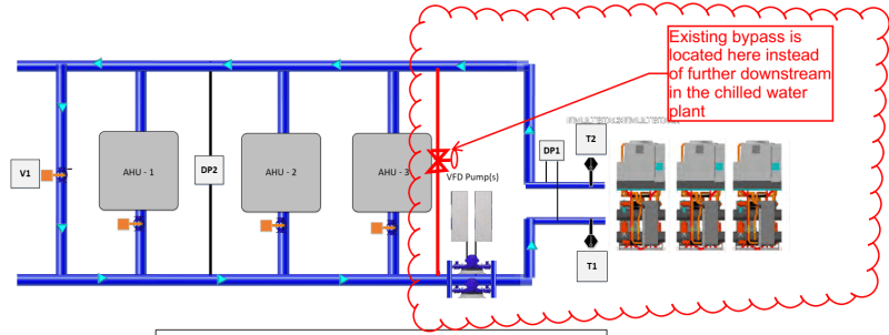

existing_chilled_water_bypass_pipe_location_btu24l.png
multistack_MagLev_chiller_performance_data_wybut4.png
multistack_chilled_water_bypass_loop_minimum_volume_requirement_chcxfo.png


Thank you,
Jo
 
Replies continue below

Recommended for you

The 2 minute min volume is to do with the time taken for the chiller package to either reduce chilling or turn the chillers off if the load suddenly went to zero.

The risk is that you would freeze the supply otherwise as the chillers kept going or had a significant thermal mass.

If the vendor wants it then the vendor gets it, or you risk invalidating your supply. It also maintains a chilled water supply past the AHUs, assuming they have reduced flow or turned flow off - you don't say how the AHUs are controlled - hence if they restart you have a reduced time before they start pumping put cold air if you put the bypass at the end of the loop.

Seems to be some discrepancy between min chiller flow (40% of max sounds about right) and a higher min figure for the bypass valve.... Don't understand that.

60 seconds isn't fast acting to me, but the PD is whatever it has to be to give you your flow rate.

I assume the control point would be the chiller DP so if flow goes down, DP goes up and bypass valve opens to maintain chiller flow?

Remember - More details = better answers
Also: If you get a response it's polite to respond to it.
 
I don't think I would try to meet the 340 gallons using piping necessarily. Typically, I always design our chiller systems with a chilled water buffer tank which kind of mixes and evens out the ups and downs of the system.
 
Thank you, LittleInch & nuuvox000 for your responses.

LittleInch,
Sorry, I should have included other basic information in the chilled water system description. It's being configured to operate as variable primary pumping system. All of the chilled water coils at the AHU's & FCU's downstream of the chilled water pumps are equipped with 2-way control valves.

The (system)DP sensor located 2/3 downstream of the chiller plant is wired to control the VFD'd CHWP, whereas the chiller DP sensor (serves as a flow meter) across the chiller is wired to the chilled water system bypass pipe control valve, which modulates to maintain the required minimum chilled water flowrates thru the chiller.

Regarding the risk of freezing due to the low thermal mass through the short (less than 2-minute) bypass chilled water loop, would replacing the farthest AHU's chilled water coil's 2-way valve with a 3-way valve solves the issue of potential freezing due to lower thermal mass in the bypass loop? We have 15% propylene glycol with freezing point of 23F.

I just found this requirement a little odd as I have seen non-magnetic bearing chillers with slower unloading capability have their bypass pipe installed within the chiller room in many places, without much issues. I would assume a maglev chiller would respond to the low load a lot faster and shuts down quicker when a low delta T is detected during low load condition.

Nuuvox000,
Thanks, I will keep that buffer tank option in mind as it would definitely add thermal mass to the bypass loop volume without running too much piping within the chiller room.


We're guessing really why the vendor wants such a large volume.

Actually there's a lot that doesn't make sense to me about data sheet.
1) If you set the chiller DP control to that figure, that implies it is set at 375GPM.
So how would you get 180GPM?
2) Why is system bypass set for 280 - where did that come from?
3) 2 minutes capacity in any condition implies 2 x 373 surely?

So I think you need to talk to someone knowledgeable in multistack or read their bulletin very closely....

Remember - More details = better answers
Also: If you get a response it's polite to respond to it.
 
just make sure to install the buffer tank in the return pipe (inlet side of chiller). I've seen it the wrong way....

3-way valve will ruin your dT, don't do that.

You'll need a flow meter to control the bybass valve. I don't think a specific dP is required. You can use a PICV.

You know, you also could talk to the Multistack rep about the specifics. I'm sure they've seen all kind of situations and can tell where you can, and where youc an't deviate from their recommendation. All their requirements are based on protecting the chillers and make the system function well. So don't deviate unless you really know what you are doing and have the OK from Multistack.

Minimum flowrates and minimum system volumes have been a requirement for chillers since they existed. This isn't specific to Multistack. With newer controls and variable capacity compressors, this can be a bit more lax. Ont he other hand, we now use larger dT (less flow). If you cheapen out on the chiller and don't get the variable capacity option, you pay more for the system. so check if you can get better chiller controls/compressor to reduce some of the piping requirements.
 
Yes, forgot to say that the 3 way valve idea doesn't sound good. Mixing control inputs into one valve will complicate life. Just control the bypass on one input and control flow into your AHU on a different input.

Remember - More details = better answers
Also: If you get a response it's polite to respond to it.
 
3-way valves were used in constant volume systems. In a variable flow system those would increase flow unnecessarily and decrease dT. They would be a very poor hack to maintain minimum flow in a chiller. i know, some people still used 3-way valves in variable flow systems, but that was based on misunderstandings.

You want the bypass far away from the chiller to have as much system as volume. Alternatively you increase buffer tank size. Sometimes it isn't practical to have the bypass valve somewhere in the system and if the design flow for bypass is high, you want it where you still have large pipes.
 
Just reading thru this and have some thoughts. I recently ran into a dort of similar situation regarding a small domestic water heating situation where a 2 minute time period was recommended as the minimum cycle time the plant should operate before setpoint was reached. We were having problems because we were reaching setpoint in around 10 seconds. The solution for that system is to install a buffer tank, but I don’t think that would be appropriate solution here. Secondly- I wonder if the two minute requirements has anything to do with the temporary supply of capacitors in the maglev chiller that keeps it operating in case of power loss. Just spit balling, but I heard a rep talk about it before.

And regarding the valve action time of the bypass valve, I imagine that keeping the time to close/open completely should be similar to the AHU valves. That might be because as you close this bypass, the whole system is connected hydraulically so you’d want to give those AHU control valves time to adjust to new pressures. Although, the CHWP is variable so when the bypass valve opens and the pressure drops at the 2/3 point, the pump should have capacity to make that pressure up again.
 
The bypass valve would modulate very slowly. It basically is controlled by the flow meter and will only close when AHU valves open up. So there is no sudden pressure change. nothing in HVAC is fast. Even VFD ramp up and down very slowly. And you have PID loops. If there are sudden changes to anything, controls are wrong.
A pump curve also is relatively flat. So a change in flow doesn't result in huge pressure changes.
 
Status
Not open for further replies.

Part and Inventory Search

Sponsor