Continue to Site

Eng-Tips is the largest engineering community on the Internet

Intelligent Work Forums for Engineering Professionals

  • Congratulations KootK on being selected by the Eng-Tips community for having the most helpful posts in the forums last week. Way to Go!

Miniumum wall thickness 1

Status
Not open for further replies.

sendithard

Industrial
Aug 26, 2021
166
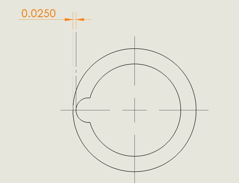
I'm having to program dimensions like this weekly. I'm not sure I've seen these type tangent to tangent dimensions in the standard, but whatever...assume it is a +-.005 here. They are a pain in the azz to make in GOM. I have two methods. Do you find the min/max of the actual features created(cylinders here), or do you find the min/max of the actual surfaces?....oh and this dimension has no datums so what is the setup you use to perform this measurment? Features would be a gage pin fit, ring gage fit, and do the math, surfaces would more surface profile distance. I ask myself what are they looking for with a tangent to tangent distance callout? Is this ASME Y14.5 acceptable, as it is an ambiguous callout from my point of view?

Then I think...why not use this type of callout to instruct for min wall thickness, instead of doing the LMC deal on the feature or the datum.
Capture_zxmeca.jpg
 
Replies continue below

Recommended for you

Just use a micrometer with a suitable anvil.

Yea, the Y14.5 committee would want to fix this up so it's not "ambiguous" but it's a directly toleranced width so perhaps it is an irregular feature of size.
 
sendithard, why do you consider it to be ambiguous?
It's comparable to the specification of a length of a rounded slot. A "set of two opposed parallel line elements" per the regular feature of size definition.

sendithard said:
Then I think...why not use this type of callout to instruct for min wall thickness, instead of doing the LMC deal on the feature or the datum.
Since the smaller arc doesn't seem to be a feature of size / good feature of size due to either lacking opposed points or being really borderline at reaching beyond 180°, position at LMC may not be relevant to it anyway.
But an interesting question would be - if the smaller radius arc was sufficiently more than 180° and dimensioned by a directly toleranced diameter (thus also considered a feature of size, a regular one) would the .025±.005 distance/size be considered a legitimate control of that features' location relative to the OD?
 
Burunduk,

What I alluding to was that if this simple tangent to tangent callout(indicating a min wall thickness) was valid why do we need these confusing LMC type callouts.
 
sendithard,
I got that, that's why I raised the question whether locating what could be considered a hole (had it been a bit less incomplete) by its edge with a directly toleranced dimension like that is legitimate. It is interesting whether this size dimension would also be considered a valid specification of the location of the hole, and only if it is, we could discuss whether it is better than position (at LMC*).

* Just a side note - LMC doesn't really preserve the minimum wall thickness any better than RFS. It just gives bonus tolerance at size conditions that would otherwise lead to a larger than the intended minimum wall thickness had the specified tolerance been applicable without the modifier and the bonus. Just thought this needs clarification, because it often feels like this point is being missed, judging by how minimum wall thickness is immediately associated with LMC as if that modifier was somehow more restrictive at preserving it.
 
RFS doesn't create a boundary making such evaluations more difficult when the form of the feature isn't perfect. This is why LMC is recommended for the task. Wall thickness can be preserved by MMC just as easily as RFS; it is similarly difficult to evaluate for features of imperfect form.

The standard needs that in the picture book.
 
With position at RFS, a worst-case boundary is also generated. It is called "Outer Boundary" or "Inner Boundary" and can be used for RFS tolerances like the Virtual Condition is used for LMC/MMC to analyze situations. Form error is not a separate factor for the analysis - it is by default included in the size limits. The OB/IB takes more than the size limits into account.

People need to get familiar with the standard so that they don't need a silly 5000 pages "picture book" to cover a portion of the infinite special cases.
 
Inner and Outer Boundary apply only to LMC and MMC conditions. Stop gaslighting people.

You are confusing this with the use of a feature as a datum reference, RMB.

 
3DDave,
Your last post is either a distraction or a misunderstanding. While the Inner or Outer Boundary does relate to the combination of the LMC or MMC size of the feature and the stated geometric tolerance, the concept applies to geometric tolerance controls at RFS.

Since you seem not to read the text and only look at pictures, open your copy of the latest Y14.5 and see "Figure 5-16 Inner and Outer Boundaries Using the RFS Concept — Internal Feature".
See what the IB and OB are? Now compare the OB in fig. 5-16 with the VC in "Figure 5-15 Virtual and Resultant Condition Boundaries Using the LMC Concept — Internal Feature". Both have the same value (because the size limits and the stated positional tolerance are the same in both figures), and both boundaries can be used exactly the same way (per the axis interpretation of position at LMC) to preserve the same minimum wall thickness.
 
Oh look another picture book entry. Well suited. Still, it fails to account for cases where the form isn't perfect.

"the collective effects of RFS and any applicable
tolerances in determining guaranteed control of
the feature center point, axis, derived median line, center
plane, or derived median plane."

No mention of boundary or surface.
 
Put a smaller diameter gage pin in the groove and measure across with caliper.
 
3DDave said:
No mention of boundary or surface

...in that paragraph.
Read the definition of Boundary, Outer in section 3. Do you know what "worst-case boundary" means?

And don't expect the standard to spoon-feed you. That is where understanding of what the controls do comes in. The examples I mentioned and the related text in the paragraphs demonstrate what the controls do. Learn from them.
 
Burunduk, it isn't the worst case except for the special case of perfect form. I am sorry the committee doesn't hand you a picture to copy and paste.
 
3DDave said:
Inner and Outer Boundary apply only to LMC and MMC conditions.

That's not true. While the boundary isn't a constant, RFS still creates an IB or OB.

John-Paul Belanger
Certified Sr. GD&T Professional
Geometric Learning Systems
 
I love the idea of a boundary that isn't constant. If it as to be evaluated on a case-by-case basis it's more of a suggestion. But that boundary is not part of the definition of an RFS controlled feature. It's just tossed in as carelessly as can be.

7.11.9 calls it "maximum external boundary" not outer boundary and "minimum internal boundary" and not inner boundary. Hmmm. Maybe they need to get their crap together.

Of course that doesn't last long before 7.11.9.1 calls it a Worst-Case Material Boundary (RMB). Then they make up an example where they don't create an accurate picture, just a bad conclusion. Specifically that the "Worst-Case Material Boundary" isn't the actual worst case given that no material will conform to the entire boundary.

At every stage where the TGC contracts around the datum feature the datum feature material is forced onto a radial line causing the boundary of the actual material in the real feature to look somewhat like the inverse of a slot - however some feature acceptance cases allow the feature by its own constraints exceed the calculated value so there's that as well. Or maybe that's not how TGCs on RFS constraints work anymore.

I can see why there is resistance to generating models based on the allowed constraints when relying on a picture book is easier to understand.
 
Belanger,
Can you clarify why you say that the boundary isn't a constant?
If we consider an internal feature such as a hole, the Outer Boundary is the large size limit (LMC) plus the tolerance value stated in the feature control frame. The Inner Boundary is the small size limit (MMC) minus the tolerance value stated in the feature control frame. The concept is mentioned only in the context of RFS tolerances, because for tolerances modified to apply at MMC or LMC the comparable boundaries are called a Virtual Condition and Resultant Condition (while the RC also takes into account the maximum possible bonus tolerance). So why the IB or OB is not a constant?
 
Can you clarify why you say that the boundary isn't a constant?
See the attached graphic. The IB or OB can be a variable (for RFS), although we're typically only concerned with the extreme number of 11.5 (the "worst-case boundary").
Yes, the VC and RC are constants (RC not constant before 2009) but those are just names for the IB or OB when they become constant.

John-Paul Belanger
Certified Sr. GD&T Professional
Geometric Learning Systems
 
 https://files.engineering.com/getfile.aspx?folder=2fa73608-fa42-4df9-adaa-fdca7b516a07&file=HoleIB.jpg
And to 3DDave's point, before 2018 the RFS figures had an asterisk note informing readers that the calculated size of OB for an internal FOS and IB for an external FOS did not include form variation of the feature.

That note is no longer in the standard which to me indicates that the committee, instead of staying on the side of mathematical/geometrical correctness, decided to impose their own quasi-mathematical rules so that everything looks nice and simple in the figures.

BTW, the same quasi-mathematical approach has been used for tolerances at MMC and LMC and the calculations of the Virtual Condition size.
 
pmarc said:
BTW, the same quasi-mathematical approach has been used for tolerances at MMC and LMC and the calculations of the Virtual Condition size.

pmarc,
Per your statement above, are you talking about this issue:

In my opinion this is another "what is in the standard vs. what (according to some) should be in the standard" type of discussion.

As of today Y14.5 clearly says that the virtual condition is a boundary generated by the collective effects of feature's specified MMC or LMC and the geometric tolerance for that material condition. In other words, if only a feature of size has MMC or LMC size limit specified, a virtual condition exists, and its size is calculated using different formulas given throughout the standard, especially in the series of figures in section 2 (2009) or 5 (2018). So why even start a discussion about it? - one camp might ask.

Well, it is because there is another camp saying that the virtual condition definition and all the VC size calculations given in the standard are artificial and don't really reflect the true worst-case sizes of the boundaries that might be created by some special as-produced geometries. If for a hole controlled with a position tolerance t at MMC the virtual condition boundary is to represent the worst-case boundary that the surface of the hole shall never violate, then this another camp will say that even with Rule #1 in charge the formula VC = MMC - t isn't fully correct because for the UAME of the hole produced at MMC size with its axis fully tilted within the position tolerance the size of the worst-case boundary will be different (smaller) than the VC size obtained by the formula. So if addtionally Rule #1 is not in charge, this makes the standard VC calculations even more incorrect.


greenimi,
Yes, that's what I am referring to.
 
Status
Not open for further replies.

Part and Inventory Search

Sponsor