Continue to Site

Eng-Tips is the largest engineering community on the Internet

Intelligent Work Forums for Engineering Professionals

  • Congratulations KootK on being selected by the Eng-Tips community for having the most helpful posts in the forums last week. Way to Go!

Miniumum wall thickness 1

Status
Not open for further replies.

sendithard

Industrial
Aug 26, 2021
166
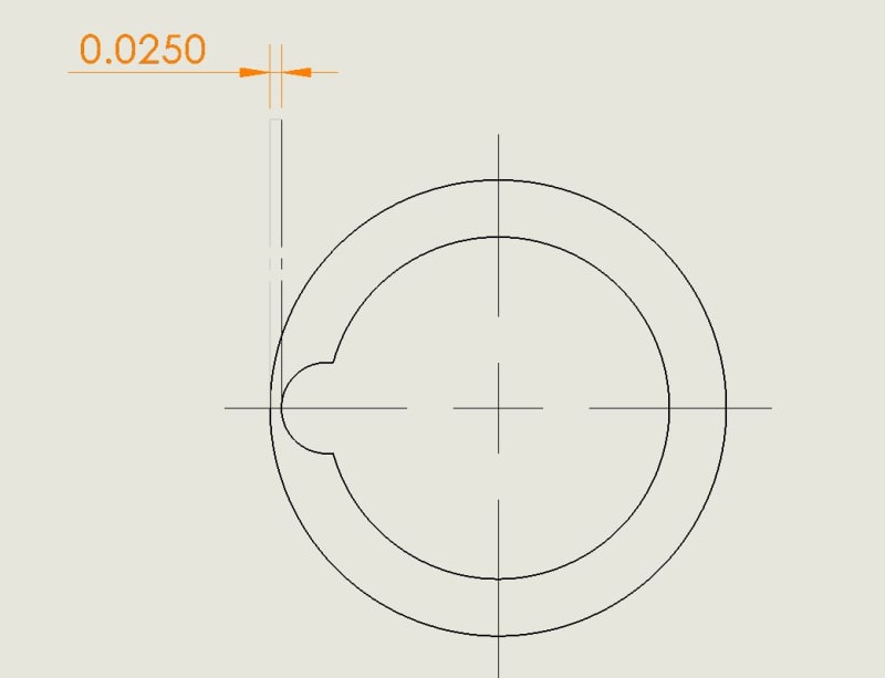
I'm having to program dimensions like this weekly. I'm not sure I've seen these type tangent to tangent dimensions in the standard, but whatever...assume it is a +-.005 here. They are a pain in the azz to make in GOM. I have two methods. Do you find the min/max of the actual features created(cylinders here), or do you find the min/max of the actual surfaces?....oh and this dimension has no datums so what is the setup you use to perform this measurment? Features would be a gage pin fit, ring gage fit, and do the math, surfaces would more surface profile distance. I ask myself what are they looking for with a tangent to tangent distance callout? Is this ASME Y14.5 acceptable, as it is an ambiguous callout from my point of view?

Then I think...why not use this type of callout to instruct for min wall thickness, instead of doing the LMC deal on the feature or the datum.
Capture_zxmeca.jpg
 
Replies continue below

Recommended for you

Belanger,
I see no support in the standard for the Inner Boundary interpretation shown in the graphic you attached.

ASME Y14.5-2018 said:
3.2 BOUNDARY, INNER (IB)
boundary, inner: a worst-case boundary generated by the collective effects of the smallest feature of size (MMC for an internal feature of size, LMC for an external feature of size) and the applicable geometric tolerance. See Figures 5-14 through 5-19.

This has been the definition of IB, and a corresponding one has been for the OB, since at least the 1994 version of the standard. As you noted, only the RC for MMC/LMC tolerances used to be a variable boundary, before 2009.
In your attached graphic, only the value of 11.5 correctly describes the Inner Boundary for the hole. See figure 5-19 in Y14.5-2018 or 2-14 in the 2009 version.
This value is calculated exactly like the VC would be, had the tolerance been specified at MMC. And it can be used for determining the worst case for assembly clearance the same way, and evaluated the same way, if the MMC tolerance requirement is evaluated per the axis interpretation.

This is why I tried to say that material condition modifiers on the tolerance value don't really do a "better job" at preserving some value of minimum wall thickness (for a hole controlled at LMC) or assembly clearance (for a hole controlled at MMC) compared to RFS requirements. They only permit more variation under the conditions that would otherwise result only in larger wall thickness (for LMC) or clearance (for MMC).

As for the effect of form error on wall thickness when the tolerance is specified at RFS as was mentioned by 3DDave and pmarc, there is a good reason why the asterisk note pmarc mentioned was dropped.
Anyone who analyzes it will realize that the deformation of an LMC-produced hole in attempt to violate the OB boundary will also affect the location of the Unrelated AME in a way that will cause the hole axis to exit the tolerance zone of position.
 
I accept that definition, and yes the 11.5 is really the only number that matters anyhow. That's what I get for firing off a reply without checking the definition section of Y14.5.
But you're getting into wordplay, I think. LMC often does a better job of controlling a min wall thickness because it allows more overall variation to the manufacturer. Thus, the function is preserved but with less cost -- that to most people constitutes doing a better job in terms of the overall design.
The main focus here is how the form error affects the boundary, so I'll avoid getting sidetracked in all the terminology. But I'm sure we can all agree that ASME does need to tighten up the vocabulary for rigor and consistency.

John-Paul Belanger
Certified Sr. GD&T Professional
Geometric Learning Systems
 
Burunduk said:
As for the effect of form error on wall thickness when the tolerance is specified at RFS as was mentioned by 3DDave and pmarc, there is a good reason why the asterisk note pmarc mentioned was dropped.
Anyone who analyzes it will realize that the deformation of an LMC-produced hole in attempt to violate the OB boundary will also affect the location of the Unrelated AME in a way that will cause the hole axis to exit the tolerance zone of position.

If I understand this correctly, you seem not to take into account a scenario where a hole has been produced at MMC almost everywhere, had a localized form error within the LMC size limit and had its UAME axis located close to or at the position tolerance zone boundary. For that condition, the OB of the hole will not be just LMC + pos. tol. and it will affect the wall thickness calculation.
 
Were the note removed "for good reason" that reason should have been added in the appendix describing the change. I see no such justification and no exhaustive demonstration that the claimed reason is true.

What remains true at every step is that RFS never controls the surface, but the surfaces are the sole consideration for a wall thickness calculation, making it an inappropriate control for that application.
 
Belanger,
Yes, I agree about "better job" in terms of reducing scrap and benefitting manufacturing by allowing more variation.
What I meant was that it is not more restrictive in keeping the feature out of a certain boundary, than RFS, when the same size limits and stated geometric tolerance apply (again, if the LMC tolerance is evaluated per the axis interpretation). That's why I said "don't really do a "better job" at preserving some value of minimum wall thickness (for a hole controlled at LMC) or assembly clearance (for a hole controlled at MMC)". But, I may have been corrected by pmarc at his last post.

pmarc, I need to think through and digest the theoretical extreme case you just described.
 
Burunduk said:
pmarc, I need to think through and digest the theoretical extreme case you just described.

Please do. I have just realized that the hole geometry I was talking about could actually look similar to the one shown in the OP's picture; the majority of the hole is at MMC but in the distance between points at 3 and 9 o'clock equals LMC. The UAME is established from the MMC portion and the UAME axis is exactly in the perfect center. So now just shift the hole in any direction such that the UAME axis lies at the boundary of the position tolerance zone and check the diameter of the outer boundary created by that feature.
 
pmarc,
I agree that this scenario is theoretically possible, but for what it's worth, I would say the circumstances of a hole produced mostly at MMC with a local size at LMC and a borderline location must be extremely rare.

I was thinking more in the direction of the absence of requirement for perfect form at LMC when the tolerance is applied at RFS, and the presense of such requirement when the tolerance is specified at LMC, and the effect of it on preserving minimum wall thickness. But, in the scenario you described, the feature doesn't even violate a hypothetical boundary of perfect form at LMC. Then suppose that for the same as-produced feature which you described, the position tolerance was specified at LMC, and was evaluated per the axis interpretation (resolved geometry method).
And suppose that the tolerances were chosen to correspond to an OB (as calculated in the standard) that protects a certain minimum wall thickness.
Would the reduction of the wall thickness to a value below the intended minimum be detected?
 
Burunduk said:
I agree that this scenario is theoretically possible, but for what it's worth, I would say the circumstances of a hole produced mostly at MMC with a local size at LMC and a borderline location must be extremely rare.

The likelihood argument is almost always brought up in cases like this. But there are also other "modes" of a real feature that could yield in having the worst-case boundary size different than the one given in the standard, including ones where the boundary of perfect form at LMC is violated. I believe we have all heard many times that GD&T is a language based on mathematical principles. In this case, though, it looks like it is based on some ASME-unique mathematical principles which don't even follow the underlying principles for the concepts which the whole language is based upon.


Burunduk said:
And suppose that the tolerances were chosen to correspond to an OB (as calculated in the standard) that protects a certain minimum wall thickness.
Would the reduction of the wall thickness to a value below the intended minimum be detected?

If it is not detected, that's even worse, because it may be "detected" by the field operating conditions of the design, e.g., when the wall won't withstand applied forces due to unintended reduction in its thickness.
 
pmarc said:
But there are also other "modes" of a real feature that could yield in having the worst-case boundary size different than the one given in the standard, including ones where the boundary of perfect form at LMC is violated.

I'm not sure about the last part. Are you?
I imagine a hole produced entirely at LMC, without tilting and at an extreme location within the position tolerance zone, touching the calculated OB. Now if that hole attempts to bend towards violating the OB in a way that corresponds with "perfect form at LMC not required", the axis of the unrelated actual mating envelope will be forced out of the tolerance zone.

pmarc said:
The likelihood argument is almost always brought up in cases like this.

The likelihood argument is not my main argument. The argument is that tolerancing at LMC suffers from the same problems as RFS, especially per the axis interpretation, which is a legitimate method of evaluation. Even if surface interpretation takes precedence in case of conflict, no one is required to double-check the axis evaluation by examining whether the surface doesn't violate the VC.
You seem not to deny that an axis inspection per an LMC requirement would not prevent the violation in the case which you described.
BTW, would you agree that for MMC and preserving clearance for assembly, the only advantage of MMC over RFS is the additional allowance, and not the ability to maintain the worst case boundary?

It is generally considered that if the manufacturer prefers the more restrictive RFS measurement over the sometimes more complex MMC/LMC evaluation (especially in the case of LMC where no physical gages can be used) it is safe to inspect at RFS, because all bad parts will be rejected anyway, even when the tolerance is specified at LMC or MMC. The same thing applies for datum features referenced with material boundary modifiers. Do you disagree with that approach?
 
Burunduk said:
I'm not sure about the last part. Are you?
Just picture a banana shaped hole that has all local sizes equal to the LMC size and the UAME equal to the MMC size. Ignoring a relation to a datum(s) for a moment, calculate the worst-case outer boundary for that hole, given the size specification is dia. 10 +/-0.1. Is it equal to LMC=10.1?

Next, plug in the locational relationship to a datum(s), say position tolerance of 0.4 at RFS, shift the feature's UAME axis to the extreme location and then calculate the size of that related outer boundary. Is it LMC+pos.tol = 10.1+0.4 = 10.5?


Burunduk said:
The likelihood argument is not my main argument. The argument is that tolerancing at LMC suffers from the same problems as RFS, especially per the axis interpretation, which is a legitimate method of evaluation. Even if surface interpretation takes precedence in case of conflict, no one is required to double-check the axis evaluation by examining whether the surface doesn't violate the VC.
You seem not to deny that an axis inspection per an LMC requirement would not prevent the violation in the case which you described.
I fully agree with this and that is why my belief for some time has been that the standard should introduce a way to graphically distinguish between the surface and axis method on the drawing. For example, the current specification method would impose the axis method only will all its geometrical inconveniences, but if someone wanted to impose the surface method it could be done for instance by using a FCF that would directly specify the size of the virtual condition boundary that shall be protected. ISO already has this allowance, but - unlike ASME - they don't have a problem with the interpretation duality because they don't define the axis interpretation for tolerances at MMC(MMR) or LMC(LMR) in their standards.


Burunduk said:
BTW, would you agree that for MMC and preserving clearance for assembly, the only advantage of MMC over RFS is the additional allowance, and not the ability to maintain the worst case boundary?
It's not the only advantage of MMC, but from the perspective of maitaning the worst case (inner) boundary I agree there is no difference. Still, this doesn't make the math correct on the other side of the feature.


Burunduk said:
It is generally considered that if the manufacturer prefers the more restrictive RFS measurement over the sometimes more complex MMC/LMC evaluation (especially in the case of LMC where no physical gages can be used) it is safe to inspect at RFS, because all bad parts will be rejected anyway, even when the tolerance is specified at LMC or MMC. The same thing applies for datum features referenced with material boundary modifiers. Do you disagree with that approach?
No, I don't, but on the stack-up analysis level it's a different story because the person doing the stack-up should consider a risk behind not including the effect of form error for tolerances at RFS. In most cases, the risk is low, as you said, and so the stack-up won't have that effect included. However, in such case not showing it is not equal to always being on the safe side.
 
pmarc said:
Just picture a banana shaped hole that has all local sizes equal to the LMC size and the UAME equal to the MMC size. Ignoring a relation to a datum(s) for a moment, calculate the worst-case outer boundary for that hole, given the size specification is dia. 10 +/-0.1. Is it equal to LMC=10.1?

No. it is not 10.1.
I think it is 10.1+0.2=10.3

How wrong am I?
 
pmarc said:
Just picture a banana shaped hole that has all local sizes equal to the LMC size and the UAME equal to the MMC size. Ignoring a relation to a datum(s) for a moment, calculate the worst-case outer boundary for that hole, given the size specification is dia. 10 +/-0.1. Is it equal to LMC=10.1?

Next, plug in the locational relationship to a datum(s), say position tolerance of 0.4 at RFS, shift the feature's UAME axis to the extreme location and then calculate the size of that related outer boundary. Is it LMC+pos.tol = 10.1+0.4 = 10.5?

I agree with the calculations, but how does that violate the Outer Boundary? Or doesn't it? The Outer Boundary per the specified tolerances is LMC + the positional tolerance = 10.1+0.4=10.5.
If this is considered to protect minimum wall thickness with RFS requirement (just like it would with LMC), then the purpose is met. Or am I missing something?
 
Burunduk,
For the given feature the unrelated OB is 10.3 and so the related OB is 10.7.

Yet the standard shows the latter should be 10.5 - this is where they come in with their own math.
 
Pmarc,
Did you setup a trap for us?
Then why Burunduk said "I agree with the calculations"
(10.1 and 10.5 were your's initial values)
 
greenimi,
I didn't want to set a trap. I truly hoped Burunduk would not agree with these calculations.
 
I'd like to clarify something about this tangent to tangent dimension...it is buried internally in a part, the only way to measure it is to section the part on a wire EDM...but we have a CT scanner that can xray these parts. That brings its own challenges.

Regardless...my real issue is our in house team is using positional tolerances on these tangent to tangent dimensions, and the two opposing curves are not coincident. These tangent contact points are ambiguous, there are only two perfectly identifiable vector points that approve of this callout, unlike a plane to plane measurement there are tons of vector points that approve.

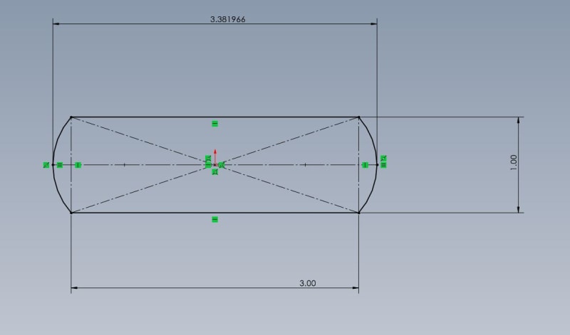
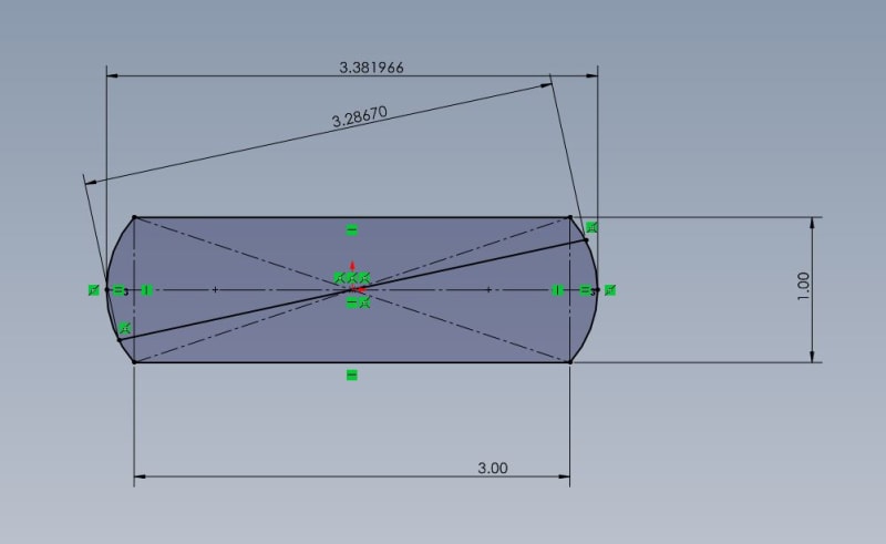
See attached drawing in solidworks.

Can you consider the tangent to tangent dimension seen below a feature of size that can accept a positional tolerance callout? I don't see how if only two perfectly placed vector points can approve this transaction.

Capture_ex4bw0.jpg


Edit.....if you were to mic this dimension at the wrong orientation things could go all wrong, depending on your mic anvil sizes or whatever you are using....this is why I don't like a tangent to tangent positional tolerance callout, but maybe I'm just too green to see how this would be repeatable.
mishit_s78ad2.jpg


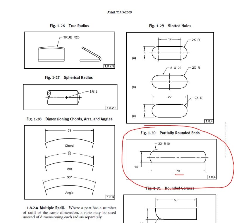
Here is an example from the standard 2009:
slots_tyiim2.jpg


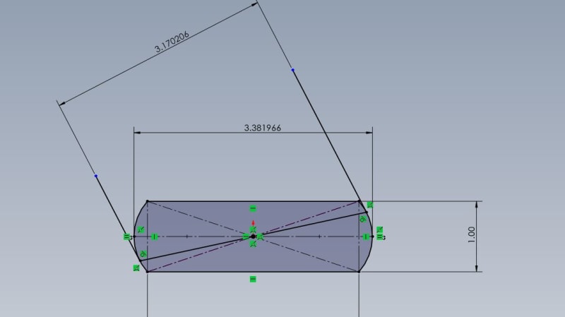
Here is a tangent to tangent incorrect measurement:
tangent_to_tangent_hysaka.jpg
 
sendithard, I've worked with drawings where tangent to tangent directly toleranced dimensions were specified. The only useful interpretation for the size limits in such cases is that you have to find the measurement orientation that maximizes the distance reading, and this reading should be in tolerance. But, to be truly unambiguous, a profile tolerance applying to both rounded surfaces would be a better choice for specification. You are right that there is a problem with applying a tolerance of position to such tangent to tangent size dimensions, because the center plane is derived from the unrelated actual mating envelope, which minimizes the separation of the parallel planes that collapse on the feature, and it will be established at an unwanted orientation.

pmarc,
Thank you for the clarification.
Indeed, there is an additional factor for the stack if a certain minimum wall thickness is intended and hole position applies at RFS. Good point. The problem is that worst case boundaries such IB, OB, and also VC really apply only on a per feature control frame basis, and other than the specific geometric tolerance, they only take into account the size limits. This makes sense as a "worst case" regarding the MMC limit side when rule #1 applies even when the tolerance is specified RFS because the form error is encompassed by the size limits, but it doesn't work that way on the LMC limit side. So ideally, either the tolerance is specified at LMC to impose the requirement of perfect form at LMC, or the form error is considered in the stack.
 
Status
Not open for further replies.

Part and Inventory Search

Sponsor