Continue to Site

Eng-Tips is the largest engineering community on the Internet

Intelligent Work Forums for Engineering Professionals

  • Congratulations IDS on being selected by the Eng-Tips community for having the most helpful posts in the forums last week. Way to Go!

Mirus Harmonic Filter

Status
Not open for further replies.

Guilhermebr

Electrical
May 3, 2015
49
Good Morning.

I would like to know, about harmonic voltage measurement on the output of the harmonic mirus filter?
 
Replies continue below

Recommended for you

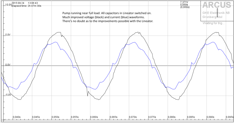
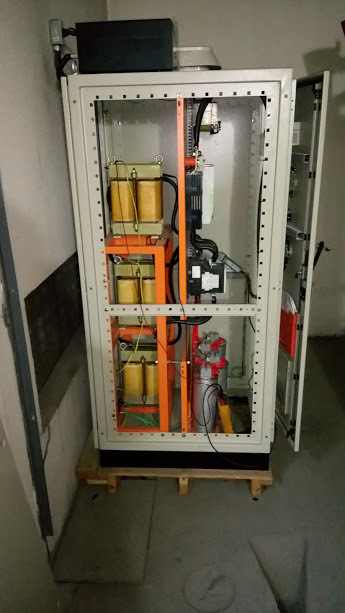
The Mirus Lineator uses an LC filter with a rather high reactance between input and capacitors. That would cause a high load sensitivity (aka bad regulation) if it weren't counteracted/compensated with a second winding that restores most of the voltage lost. It works quite well, but there is a certain risk that you get resonance phenomena at low load and that can cause DC link overvoltage if the Lineator feeds a VFD, which is almost always the case.

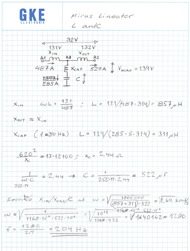
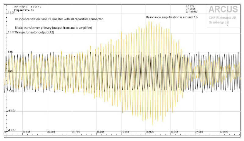
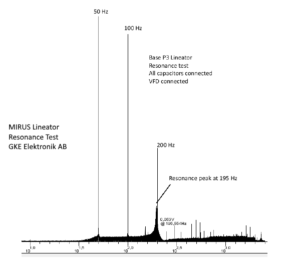
The filter works very well at full load, but you have to take the resonance risk into account. I will try and add a few measurements and calculations that show behavior of a 1600 kVA Mirus Lineator. It may be necessary to post several times. So, if you do not see what you expect in the first posting, go to the next ones.

Mirus_Lineator_100_percent_load_1_fxazkm.png


Mirus_Lineator_resonance_frequency_at_low_load_1_lzpooo.png


Mirus_Lineator_resonance_test_at_low_load_waveforms_1_f4tlbz.png


Mirus_Lineator_resonance_test_at_low_load_1_zrgejn.png


Gunnar Englund
--------------------------------------
Half full - Half empty? I don't mind. It's what in it that counts.
 
Thanks for the answer.

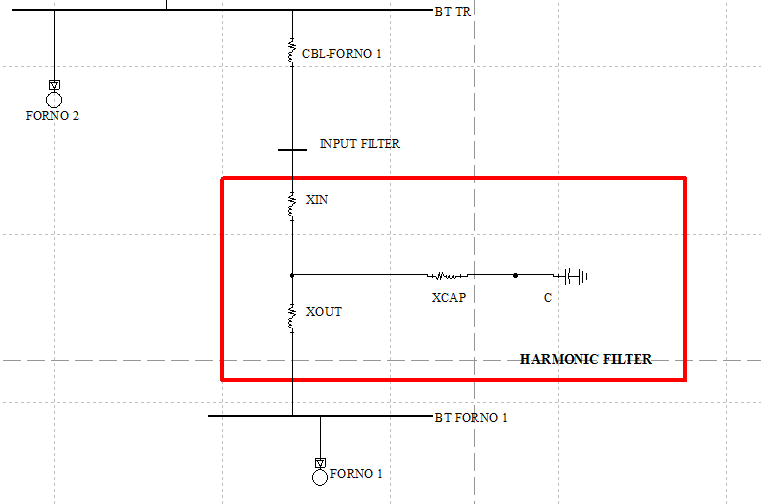
Normally I use shunt tuned filters that I design, like the image, and installed at the output of a transformer or generator. I've rarely used active filters.

I was thinking and looking for another solution, to use together with VDF and DRIVES passively, so I found Mirus and MTE.

About your image and calculations:
- the voltages and currents of Xin and Xout are at 50Hz?
- the voltage and current of Xcap at 250Hz?
- What is the nominal voltage of the system?

I used your data in a simulation, and found resonance peak around 130Hz, maybe my data is wrong.

When the load is too low, can the voltage increase from + 10% at point A3 according to its design? do you have some measurement about it?


I used in the simulation:
Xin = 0.299 ohms for 50Hz
Xout near Xin
Xcap = 0.0976 ohms for 50Hz
C = 2.44 ohms for 50Hz

shunt tuned harmonic filter
TUNED_HARMONIC_FILTER_ppzbvy.jpg


circuit
Ressonance_Draw_ub6evq.png


ressonance paek
Ressonance_e3uoft.png
 
Your comments, with my comments (in blue)
added:

Normally I use shunt tuned filters that I design, like the image, and installed at the output of a transformer or generator. I've rarely used active filters. Nor do I. And the Lineator isn't an active filter, either.


I was thinking and looking for another solution, to use together with VDF and DRIVES passively, so I found Mirus and MTE.

About your image and calculations:
- the voltages and currents of Xin and Xout are at 50Hz? Yes
- the voltage and current of Xcap at 250Hz? The measurements were made on site "in the jungle" using crude tools, like a clamp meter and a simple volt-meter. So the data at different frequencies are not available. The dominating frequency at C is 250 Hz and that was used to get a rough estimate of XC.
- What is the nominal voltage of the system? Nominal voltage is 690 V. The taps were set at 655 V

I used your data in a simulation, and found resonance peak around 130Hz, maybe my data is wrong. The result is VERY dependent on load and how Xin and Xout (common core, common flux) are connected. They shall be connected with opposing polarities. My recordings were made at zero load on the output


When the load is too low, can the voltage increase from + 10% at point A3 according to its design? do you have some measurement about it?The Lineator does not cause much overvoltage at low loads. The reason for this is that Xin and Xout makes a relatively low C possible. The draw-back is that unexpected resonances occur at "unusual" frequencies. Like what you get when there is sympathetic inrush present. In such a situation, the output voltage can easily take the DC link voltage up to values that makes the capacitors explode.


Gunnar Englund
--------------------------------------
Half full - Half empty? I don't mind. It's what in it that counts.
 
Hi.

Thanks for your answers.

I will make some testing, and if possible, I'd like to share the results.

________________________
Guilherme Schallenberger.
Electric Service.
Brazil.
 
Hello Gunnar;

You mentioned that Xin and Xout are phased in opposite directions, but loosely coupled. Do you have a feel for what the mutual inductance is?
 
No, not loosely coupled. Firmly. The whole idea is to "lift" the lost voltage in Xin back with Xout.
Talk to Mirus for more details. My task was to find out why a bunch of 1200 kW VFDs exploded. No design work or such from my side.

Gunnar Englund
--------------------------------------
Half full - Half empty? I don't mind. It's what in it that counts.
 
Hi Gunnar

Do you know about the differences Mirus Lineator for use with Load "Diode Bridge Rectifier - Model D" or "Thyristor Bridge Rectifier - Model T" ?
 
No, I have only seen the one that works with ordinary diode rectifiers.
I think that you should contact Mr Tony Hoevenaars at Mirus for more information.

Gunnar Englund
--------------------------------------
Half full - Half empty? I don't mind. It's what in it that counts.
 
Hi Gunnar

In your measurements with the mirus lineator.

Xin inductance have variation without load(VFD OFF an CAP ON), and full load (VFD ON and CAP ON)?
 
Status
Not open for further replies.

Part and Inventory Search

Sponsor