Continue to Site

Eng-Tips is the largest engineering community on the Internet

Intelligent Work Forums for Engineering Professionals

  • Congratulations IDS on being selected by the Eng-Tips community for having the most helpful posts in the forums last week. Way to Go!

Model Meshing Issues

brut3

Structural
Mar 9, 2010
58
I have a relatively simple part that I'm trying to run a stress analysis on. When trying to mesh the part I'm receiving an "unable to mesh part" error message. Additionally, there is nothing reported on the mesh error report. I've attached the part for your use, any help would be greatly appreciated.
 

Attachments

  • Curved Metal Panel.zip
    319.1 KB · Views: 4
Replies continue below

Recommended for you

I have Inventor but not your version. post STP file
 
meshed ok for me (using FeMap). what are you using ? PATRAN ?
 
Hello brut3. Can you show us pictures of your mesh or describe what type of mesh you want to get? Maybe you try to create solid mesh on this thin walled part and get errors.
 
Dear Brut3,
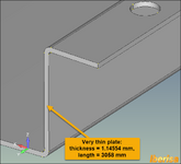
This is a very thin plate, then is crazy to mesh using 3D solid elements (to account for stress gradient you need to mesh with minimum TWO elements in the thickness), the correct meshing workflow should be to create a midsurface and mesh with 2-D Plate/Shell CQUAD4 elements:

very-thin-plate.png

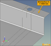
In fact, here you have the MIDSURFACE created in FEMAP V2406 MP1 ready to mesh with 2-D Plate/Shell elements (please note the curve imprints created in the midsurface to allow to generate automatic mapped mesh with excellent quality using the Approach on Surface = mapped four coner feature):

midsurface-created-in-FEMAP.png

Mesh in FEMAP with the MESHING TOOLBOX using an element size = 6.35/4 = 1.5875 mm.
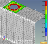
The quality of mesh is excellent: Jacobian check =0.387, well below the maximum allowable threshold (the limit is 0.6)

midsurface-mesh-quality.png

In summary: the target is to mesh with 2D Plate/Shell elements. Please note the plate thickness is very small, then a linear static analysis surely will be useless, the correct analysis type should be NonLinear activating large displacement effect to account for stress stiffneing effect (ie, account for membrane stiffness).

Best regards,
Blas.
 
agree 100% with Blas, this part should be modelled with shell elements.
 

Part and Inventory Search

Sponsor