lexeng18
Structural
- Jul 5, 2018
- 45
Hi all,
I have a situation where I need to reinforce a few interior columns in a large warehouse for new axial load due to large RTUs and associated snow drifts. The columns are pinned at the base by a standard baseplate and restrained laterally at the top by a flexible diaphragm. Due to obstructions of process equipment, I designed partial height plate reinforcement for these columns. The plate reinforcement extended from FFE to 14'-0", while the total column length is 30'-0". I originally approached the design as a stepped column analysis. I recently went to compare the results of my stepped column analysis to that of a linear buckling analysis from RAM Elements.
I understand that the results from the linear buckling analysis need to be modified in some way to account for things such as initial imperfections and inelastic buckling behavior. However, the proper implementation of these effects are causing me confusion. I have seen examples on this forum of backing out an appropriate K value from the Euler buckling equation if the buckling load is known, however this is only possible if the cross section is constant along its length. In my case, it varies.
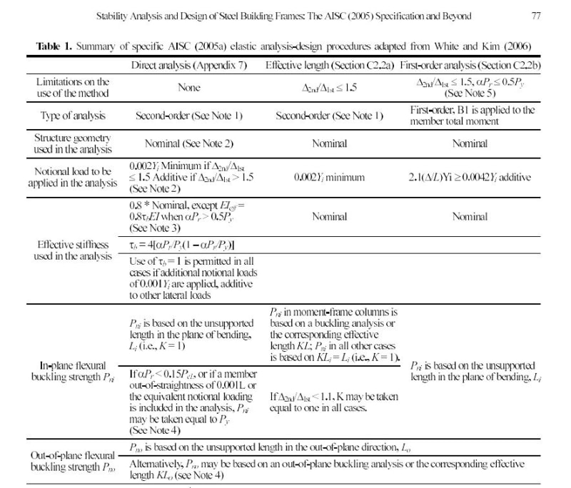
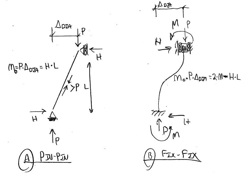
Therefore I believe the only way to properly design these columns is to use the DAM procedures. I have no issue reducing the material stiffness of the column by 0.8 * tau_b which of course reduces my buckling load. However, the modeling of initial imperfections is causing me issues. If I attempt to use notional loads, the buckling load is unaffected by the small lateral force that I am applying at mid-height of the column. Is the proper procedure to use the beam-column interaction equations to check the column for unity considering the buckling load with a reduced stiffness material property and the moment due to the notional load? If so, I'm not sure how the fact that the column is partially reinforced would affect the flexural capacity of the column. What I mean is, while the software is accurately capturing the effects of varying stiffness cross section for the axial condition via the buckling analysis, it is not considering it for the flexure condition.
Am I going about this in the wrong way? Should I be modeling direct displacements in the nodes to account for the initial imperfections in the column instead of notional loads due to these issues?
I have done a great deal of searching on this topic before posting and feel that previous discussions on this topic did not address the varying cross section situation in a way that I understood. I would be happy to provide more information or sketches if it is helpful to facilitate discussion.


