-
1
- #1
VN1981
Aerospace
- Sep 29, 2015
- 186
Hi,
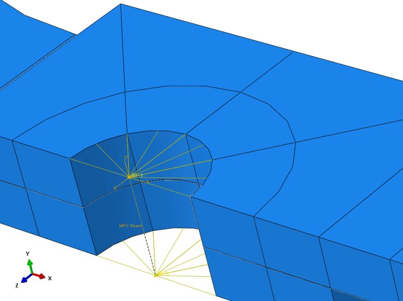
I am trying to model a Lap Joint with Holes connected by a Bushing element and coupling elements.
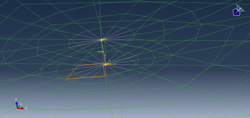
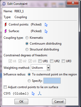
The wire represents the fasteners and is assigned Bushing connector elements with Elastic stiffness (or flexibility) defined. The fastener element is connected to respective plates (top & bottom) via Distributed coupling.
A tensile load is applied to the top plate while the corresponding opposite end is fixed on the bottom plate as shown below:

However, the analysis gets aborted when I run it. The message files says
"
***NOTE: THE SOLUTION APPEARS TO BE DIVERGING. CONVERGENCE IS JUDGED UNLIKELY.
***ERROR: TOO MANY ATTEMPTS MADE FOR THIS INCREMENT"
I have attached zip file containing the job analysis message file. Also there were several warnings of singularities. I suspect some how there is Rigid body motion happening!
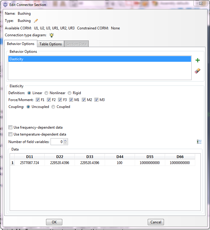
ALso, I am inserting images of my Bushing Connector & Distributed Coupling Settings entry in Abaqus CAE
Note: 1) The above problem setup runs fine in Nastran i.e. using RBE3 MPC with CBUSH (Sring/DOF element) for fasteners. I thought I could replicate the same modeling method in Abaqus.
2) I did a much more simpler Lap Joint model but without holes and used Fastener connection in Abaqus with everything else remaining the same (except for manually created couplings) and analysis ran fine with no errors and expected outputs.
I would really appreciate help with the above issue.
Thanks...
I am trying to model a Lap Joint with Holes connected by a Bushing element and coupling elements.

The wire represents the fasteners and is assigned Bushing connector elements with Elastic stiffness (or flexibility) defined. The fastener element is connected to respective plates (top & bottom) via Distributed coupling.
A tensile load is applied to the top plate while the corresponding opposite end is fixed on the bottom plate as shown below:

However, the analysis gets aborted when I run it. The message files says
"
***NOTE: THE SOLUTION APPEARS TO BE DIVERGING. CONVERGENCE IS JUDGED UNLIKELY.
***ERROR: TOO MANY ATTEMPTS MADE FOR THIS INCREMENT"
I have attached zip file containing the job analysis message file. Also there were several warnings of singularities. I suspect some how there is Rigid body motion happening!
ALso, I am inserting images of my Bushing Connector & Distributed Coupling Settings entry in Abaqus CAE


Note: 1) The above problem setup runs fine in Nastran i.e. using RBE3 MPC with CBUSH (Sring/DOF element) for fasteners. I thought I could replicate the same modeling method in Abaqus.
2) I did a much more simpler Lap Joint model but without holes and used Fastener connection in Abaqus with everything else remaining the same (except for manually created couplings) and analysis ran fine with no errors and expected outputs.
I would really appreciate help with the above issue.
Thanks...

