Eng-Tips is the largest engineering community on the Internet

Intelligent Work Forums for Engineering Professionals

  • Congratulations waross on being selected by the Tek-Tips community for having the most helpful posts in the forums last week. Way to Go!

Modelling a Soft Ground

Status
Not open for further replies.

Nick7805

Mechanical
Nov 19, 2021
21
0
0
CA
Hello,

I'm looking for a method to model the effect of a soft ground below the base of a steel hopper-bottom silo. I have the silo modeled in Inventor Nastran. As I understand, creating a CAD model for the ground and using contacts isn't an appropriate way to do this because of the large difference in stiffness. Likewise, constraints aren't appropriate since the ground is soft.

Does anyone have any suggestion for how to take into account the ground? Thanks in advanced.
 
Replies continue below

Recommended for you

If you don’t want to model the ground itself, you can define the elastic foundation (assuming that your software allows for this).
 
Thank you for the suggestion FEA way, but I believe that's not possible on Inventor Nastran. The closest option is a spring connection, but that only allows for point-to-point connection, yet I have an entire base surface. Do you have any other suggestion?
 
Theoretically, you could define a discrete spring for each node of the bottom surface but that only makes sense when you can script the whole setup. However, according to the Autodesk knowledge base article, there is a workaround - use a rigid connector to attach the surface to a spring connector which in turn is attached to the ground point.
 
I am not familiar with Inventor Nastran, but would a solution proposed by FEA way enforce all the foundation nodes to move the same, i.e. as a rigid body. I am assuming that the whole point is to get internal forces and moments in the foundation and this might not provide that. I think that you probably need to have an individual spring attached to each foundation node, the other end of the spring restrained. Can you not do it in, say, Excel and include in the input deck?
 
Hi bkal,

The point isn't to analyze the foundation, it's to analyze the structure that rests on the foundation while accounting for the support the foundation provides to the base of the structure. In this case, I don't see a big issue. However, despite this, I think that this method of using a rigid connector and grounded spring may not give the most accurate results for the same reason you're indicating.

I'm not familiar enough with Inventor Nastran to know if modifying the input file data is possible (this is what you meant, correct?), but I'm going to keep in mind for the future. I'd love to have that level of control over the simulation; it would open up tons of possibilities not possible via the software's user interface.
 
If that is the case, Nick, why do you need to model the ground? You foundation slab in the model would displace as a rigid body, so the only effect captured by modelling the ground would be average settlement. There will be no moments or internal forces in the foundation slab so you will need to use different approach to design it. If that is what you are planning, than just do it.
 
Hi Bkal,

The purpose isn't to design a foundation as the structure simply sits on the ground. The structure is a silo and I'm interested in knowing the stress in the metal base of the silo. If I didn't model the ground and instead fixed the base in my simulation, I wouldn't find the stress in the base, as the thin metal base is modelled using shell elements.
 
I am assuming that your metal base is bearing on the ground. I am not sure how Nastran works, but it is possible that if you use rigid links to connect nodes of your metal base to a single node, then all the metal base nodes would displace as a rigid body. If that is the case, you will not get sensible (or any) stresses in your base.
 
I agree with you Bkal, except for the fact there's contacts set with other components in the structure that connect to the base. I believe that these should cause some stress in the base regardless of the rigid body constraint -- but I won't know for sure until I get to that point.

I'm going to try modelling the ground/base using contact, however I'm concerned that my model won't converge. I've simplified as best as I could, but there's already a lot of contacts within the model.
 
Hey Nick.

I use Inventor Nastran, I also happen to deal with steel hopper-bottom silos quite regularly. What exactly are you trying to achieve or design with you model? What diameter silo is it? I ask because at first assessment it doesn't seem like you are using the right tool for the job. That said it isn't clear what your job and goal is so I can't really comment apart from that I know this subject matter pretty deeply so I am curious.

When you say hopper bottom silo is this a silo with a hopper but with a skirt support bearing on the foundation in a continuous sheet ring as opposed to a hopper bottom with discrete leg support for the last few meters?
 
Hey @human909,

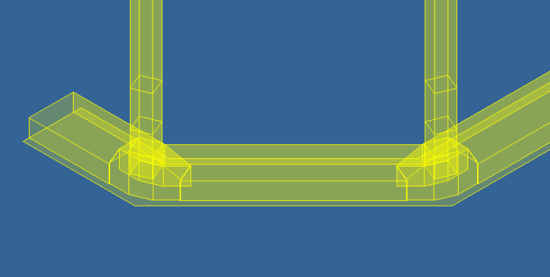
So my job is to model a hopper bottom silo with non-linear FEA with loads calculated as per EN 1993-4-1, and optimize the components to reduce material costs. The hopper/silo is supported the last few meters by legs. I'm new to the industry and happy for advice and suggestions. This is what the base looks in my mid-surface model:

base_ivzqel.png
 
Nick7805 said:
So my job is to model a hopper bottom silo with non-linear FEA with loads calculated as per EN 1993-4-1, and optimize the components to reduce material costs. The hopper/silo is supported the last few meters by legs. I'm new to the industry and happy for advice and suggestions. This is what the base looks in my mid-surface model:

This sounds like an extremely complex task and best approached by looking at very specific areas at a time. Your model seems to indicate that you have hollow section columns and no lateral bracing which is quite a surprising design. Is this actually how the silos you are dealing with are designed?

Back to your original question. I would be modelling the surface contacts as a stiff foundation, though typically you'd consider pinned connections to the foundation. Silo foundations are generally very rigid due to size require to both spread the load and simply to resist overturning from wind when empty.

Going back a couple of steps. What part of the silo are you focussing on in this model and how much of the silo do you intend to model?


My background. I've designed various hoppers of various shapes to EN1993-4-1. I've also had to review OEM silos to ensure that they actually comply to EN 1993-4-1.
 
Thank you for taking your time here human909, I appreciate it very much.

These bins are for grain and fertilizer storage. And yes, the modelling reflects the design, which has been being used for a long time. When you say lateral bracing, are you referring to bracing in the radial direction, or bracing between the legs?

I agree it is a complex task, but my work is supervised by a senior engineer and based on previous work; I'm under the senior engineer's directive.

My task is to model the complete bin in a SINGLE simulation, performing non-linear static and buckling analysis'. I've worked out the bugs in the model by simulating the model with each new part I add to make sure behavior (trends, stress, displacement, contacts, etc.) is as expected before moving on to the next part (for example, I added the legs and tested with various simulation types to work out any errors and unexpected behavior, before beginning on the base). I'm working on modelling the effect of the ground now.
 
Hi

I know I am a bit late in the discussion. But Inventor Nastran used to (I think) be Autodesk Nastran and that was NEiNastran. That should allow you to model the ground (soil) with volume elements and assuming that you model the base of the silo with plate elements, surface contact should be able to solve the issue.

I noticed the concern that the model won't converge. That is always a possibility for that in a non-linear analysis but usually you have to test.

My main concern would be how to model the soil to get the appropriate stiffness. The soil, in reality, will be a huge volume so how to get the correct stiffness can be challenge. Usually I would work with two stiffness values, one reasonably high and the other reasonably low.

But I may have misunderstood the problem entirely [smile].

Good luck

Thomas
 
Status
Not open for further replies.
Back
Top