jaskamakkara
Structural
- May 27, 2020
- 35
Hi everyone,
I am checking a steel crane beam in an old theater. It is about 21m long and is supported in 3 intermediate points for 4 continuous spans of approx 5m. It is connected at these points to perpendicularly spanning concrete beams by way of channel sections, welded vertically to the top of the steel beam either side of the concrete beam, bolted to the concrete. The concrete beam is about 380mm wide so there is that much distance between the channel sections at these points.

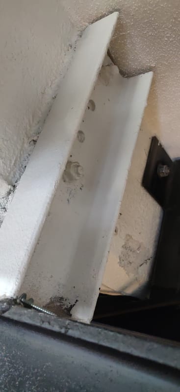
Here you can see the channel on one side of a concrete beam.
To get the proper buckling capacity of this crane beam I decided to do a proper 2d element stability analysis since I wasn't sure how to get the buckling length from first principles given the nature of these connections and I wanted to capture the lack of proper torsional restraint at these locations. But this then made me realise that modelling these channels individually (rather than condensing each pair of channels to a single support) meant that I was getting some lever action and the support reactions are much higher than they would be if I condensed the supports to single points. The problem is now that the support capacity is driving the check and I'd prefer to get some more capacity out of these beams if possible. I suspect that if I were able to model the bolt connections as very stiff springs it might alleviate the issue a little bit, but I'm not sure how to put a number on it.


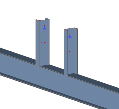
Snippets from my model

Difference in support reactions between modelling supports separately, and condensed. The 2d model agrees well with this 1d model.
Question is do you think it's reasonable to model the connections like this? I'm finding it hard to argue with the results since the FEM gives the "real" situation and these channels are spaced sufficiently far apart that I think they will behave more like separate supports. But, then again, when you have a seated connection with 2 pairs of bolts 200mm apart you would always treat that like a single support since otherwise the lever action would be huge and artifically increase your bolt forces. What do you think?
Cheers
I am checking a steel crane beam in an old theater. It is about 21m long and is supported in 3 intermediate points for 4 continuous spans of approx 5m. It is connected at these points to perpendicularly spanning concrete beams by way of channel sections, welded vertically to the top of the steel beam either side of the concrete beam, bolted to the concrete. The concrete beam is about 380mm wide so there is that much distance between the channel sections at these points.

Here you can see the channel on one side of a concrete beam.
To get the proper buckling capacity of this crane beam I decided to do a proper 2d element stability analysis since I wasn't sure how to get the buckling length from first principles given the nature of these connections and I wanted to capture the lack of proper torsional restraint at these locations. But this then made me realise that modelling these channels individually (rather than condensing each pair of channels to a single support) meant that I was getting some lever action and the support reactions are much higher than they would be if I condensed the supports to single points. The problem is now that the support capacity is driving the check and I'd prefer to get some more capacity out of these beams if possible. I suspect that if I were able to model the bolt connections as very stiff springs it might alleviate the issue a little bit, but I'm not sure how to put a number on it.


Snippets from my model

Difference in support reactions between modelling supports separately, and condensed. The 2d model agrees well with this 1d model.
Question is do you think it's reasonable to model the connections like this? I'm finding it hard to argue with the results since the FEM gives the "real" situation and these channels are spaced sufficiently far apart that I think they will behave more like separate supports. But, then again, when you have a seated connection with 2 pairs of bolts 200mm apart you would always treat that like a single support since otherwise the lever action would be huge and artifically increase your bolt forces. What do you think?
Cheers
