BorisGeorgiev93
New member
Hello, everyone!
My question is related to contact sections in Abaqus, when models of composite laminates are created and loaded only in compression at both ends.
First of all, here is a brief introduction of what I am doing:
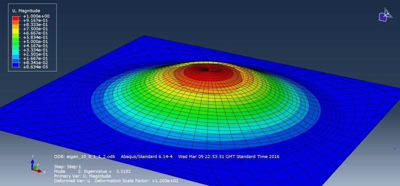
I have created in Abaqus a model of a composite laminate which has experienced a low velocity impact with an object. My model represents a square plate. As a result of this impact, some of the layers have, in a certain region, been delaminated and hence the entire composite laminate can be considered to consists of 2 'parts': 1) The sublaminate, contains the delaminated layers and 2) the base laminate, where all the layers are flat (undamaged/intact). I apply only compressive loading and run a non-linear RIKS analysis in order to investigate the post-buckling response of the entire laminate. Regarding the sublaminate, I have modelled the delaminated region as a SIN half-wave that is clamped at its two ends. The delaminated region itself is circular with a diameter of 30mm.
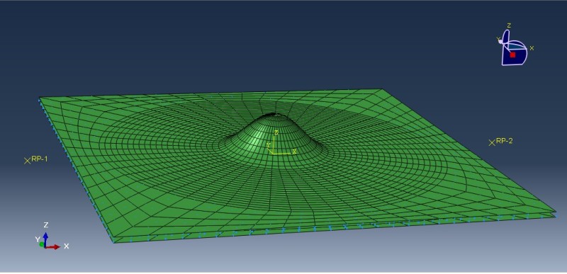
The image below shows exaggerated delamination in order to facilitate observation. I hope you can also see the 2 element layers that are in the model. The bottom element layer represents the baselaminate, while the top one represents the sublaminate. Exactly the same mesh is used for both element layers. Also, I use 2D shell elements -> S8R5. If I analyse a laminate that has 21 plies, the sublaminate may contain maximum 5 or 6 layers( in other words, it is assumed that the delamination can reach only 25% of the total thickness of the laminate )
The region between the outermost circle and the 4 edges of the square plate is anti-buckling guide, meaning that buckling is only possible within the circular region. The whole idea behind the creation of this finite element model is to resemble, as accurately as possible, axil compression tests that are done by research groups. These test feature compression fixtures with anti-buckling guide.
Can someone give a piece of advice, whether I should include contact section OR contact interaction between the sublaminate and the baselaminate. If I have to do that, then in what region of the above model should this contact section be included -> 1) only the elements in the circular region (where buckling is allowed) OR 2) the entire model? All I want is to have as much accurate model as possible. A model that represents real compressive loading of a composite laminate coupon.
Thank you in advance for your time,attention and understanding!
I hope that I have made my explanation clear enough!
Really hope that someone can share his/her opinion on the matter.
With Respect!
Boris Georgiev
My question is related to contact sections in Abaqus, when models of composite laminates are created and loaded only in compression at both ends.
First of all, here is a brief introduction of what I am doing:
I have created in Abaqus a model of a composite laminate which has experienced a low velocity impact with an object. My model represents a square plate. As a result of this impact, some of the layers have, in a certain region, been delaminated and hence the entire composite laminate can be considered to consists of 2 'parts': 1) The sublaminate, contains the delaminated layers and 2) the base laminate, where all the layers are flat (undamaged/intact). I apply only compressive loading and run a non-linear RIKS analysis in order to investigate the post-buckling response of the entire laminate. Regarding the sublaminate, I have modelled the delaminated region as a SIN half-wave that is clamped at its two ends. The delaminated region itself is circular with a diameter of 30mm.
The image below shows exaggerated delamination in order to facilitate observation. I hope you can also see the 2 element layers that are in the model. The bottom element layer represents the baselaminate, while the top one represents the sublaminate. Exactly the same mesh is used for both element layers. Also, I use 2D shell elements -> S8R5. If I analyse a laminate that has 21 plies, the sublaminate may contain maximum 5 or 6 layers( in other words, it is assumed that the delamination can reach only 25% of the total thickness of the laminate )
The region between the outermost circle and the 4 edges of the square plate is anti-buckling guide, meaning that buckling is only possible within the circular region. The whole idea behind the creation of this finite element model is to resemble, as accurately as possible, axil compression tests that are done by research groups. These test feature compression fixtures with anti-buckling guide.
Can someone give a piece of advice, whether I should include contact section OR contact interaction between the sublaminate and the baselaminate. If I have to do that, then in what region of the above model should this contact section be included -> 1) only the elements in the circular region (where buckling is allowed) OR 2) the entire model? All I want is to have as much accurate model as possible. A model that represents real compressive loading of a composite laminate coupon.
Thank you in advance for your time,attention and understanding!
I hope that I have made my explanation clear enough!
Really hope that someone can share his/her opinion on the matter.
With Respect!
Boris Georgiev