Continue to Site

Eng-Tips is the largest engineering community on the Internet

Intelligent Work Forums for Engineering Professionals

  • Congratulations KootK on being selected by the Eng-Tips community for having the most helpful posts in the forums last week. Way to Go!

Modelling Different Flange Thicknesses welded together 1

Status
Not open for further replies.

Error.n.n

Structural
Aug 31, 2023
19
Hello,

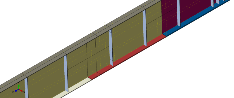
I am creating an Abaqus model of a steel girder that is made of parts with different thicknesses for the flanges and web. I am using shell elements. The girder is 100m long and comprises of three different sections with uniform flange and web thicknesses. I used merge instances to create join the sections of the girder and create the 100m. The webs merged well however the flanges have a gap since I am using shell elements. I used tie constraints to create a connection between the two flanges with different thicknesses. However, I was wondering if there was another way to model this are to produce trusted results. in the real structure, these sections are welded together.
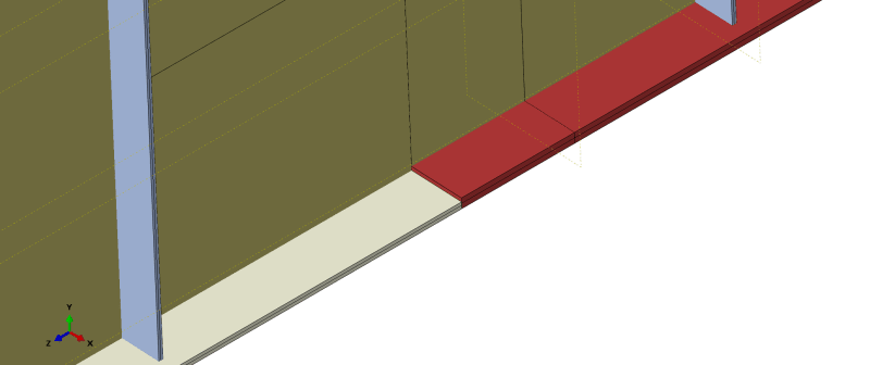
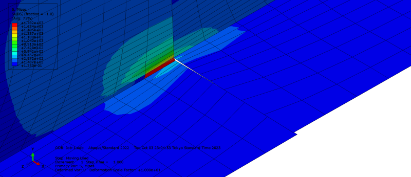
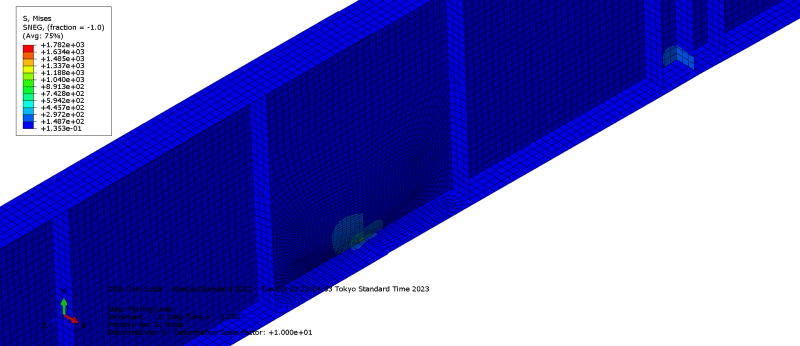
Shell_connection_detail_one_girder2_mlfxeh.png
Shell_connection_detail_one_girder_o7pmj5.png
Shell_connection_detail_one_girder3_wgxsfr.png
Shell_connection_detail_one_girder4_emjlvz.png


Or is this way of modeling sufficient and adding constraints sufficient?
 
Replies continue below

Recommended for you

constraints ? "surely" you just model the flanges with common nodes, and two (or three) element properties (defining different thickness). no ??

"Hoffen wir mal, dass alles gut geht !"
General Paulus, Nov 1942, outside Stalingrad after the launch of Operation Uranus.
 
Hi,

Hmm, I get what you mean. But that is difficult to do. The web heights vary slightly, and they must be all connected along their overall centerlines of the total girder height of 1600mm (the girder height is the same for all the sections, but the web heights and flange thicknesses vary) to achieve the detail in the drawing. So I have to create different parts; the only common nodes are along the web after merging the part instances, but not the flanges. I am using shell elements (thickness extruded from middle section)

I have attached sketches of what I mean and the actual details of the connections to the girder sections. Is there another way that I am missing, perhaps?
 
 https://files.engineering.com/getfile.aspx?folder=40c36e56-b005-4d76-94e9-486aaa635bd8&file=Drawing1-Model.pdf
That approach is way too complicated and a waste of time. Just put a line of nodes at the centerline of the thinnest flange area and use that full length. Then put appropriate thicknesses for elements in each region.

 
Hello,

My focus is mostly on the stresses at the thickness change to the utmost accuracy I can achieve using shell elements. This approach would give me slightly different results. However, thank you, SWcomposites and rb1957 for the insight. I know how to fix the issue now.
 
Well, that makes no sense. If you are interested in detailed stresses at the thickness change (and I have no idea why you would be) using shell elements is not going to get you anywhere close to that.

And if you really are interested in those detail stresses, for heaven’s sake you don’t need to model the entire beam.
 
Timoshenko "Plates and Shells" might have something on the stresses at a step.

"Hoffen wir mal, dass alles gut geht !"
General Paulus, Nov 1942, outside Stalingrad after the launch of Operation Uranus.
 
and your mesh looks way too coarse to pick up much of the detailed stresses at the step

"Hoffen wir mal, dass alles gut geht !"
General Paulus, Nov 1942, outside Stalingrad after the launch of Operation Uranus.
 
hi,

The reason I am modelling the full structure is because I want to determine the influence surfaces for stresses at that section point where the thickness varies. Maybe you are right, and I am approaching the problem the wrong way. I am carrying out a study of fatigue analysis of critical components of a bridge using real live traffic data. Instead of using influence lines, I wanted to approach the problem using influence surfaces (hence FEA and shell elements) as opposed to the standard beam models. Also, influence lines and surfaces require the full girder to be modelled.

My thinking was that if I could get well-defined plate elements, then I could apply the concepts from this paper, "A. Cifuentes, M. Paz, Determination of Influence Lines and Surfaces," to get the influence surface. Thank you for the book recommendation. Yes, I will revise the mesh accordingly.

My apologies; I am relatively new to the concepts of FEA and ABAQS modelling, and so I appreciate your suggestions and directions for further study. Feel free to redirect my approach.
 
You could use a mixed mesh (shell-to-solid coupling will let you connect shell and solid regions) or submodeling to get accurate results for that area of interest.
 
Isn't there a standard Kt associated with a thickness step change ? Wouldn't that be a more direct way to evaluate fatigue issues ?

"Hoffen wir mal, dass alles gut geht !"
General Paulus, Nov 1942, outside Stalingrad after the launch of Operation Uranus.
 
Status
Not open for further replies.

Part and Inventory Search

Sponsor