BritMechEng
Mechanical
- Jul 15, 2019
- 2
Hello all, this is my first professional post so really don't know how it works and recently graduated in mechanical engineering.
Along my new professional career, I'm working in FEA and I've been training by modelling some simple stuff and more complex ones.
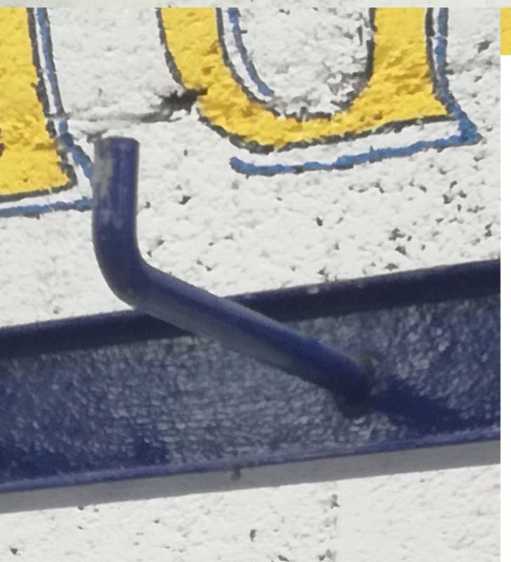
This one is a bit tricky since I've tried to create a simple model of a hanger for lifting slings (you can see its picture below).

As you can see, it seems like there's a shaft of roughly 100 mm long and an arc supposed to be 25mm radius. This is the hypothesis I went with.
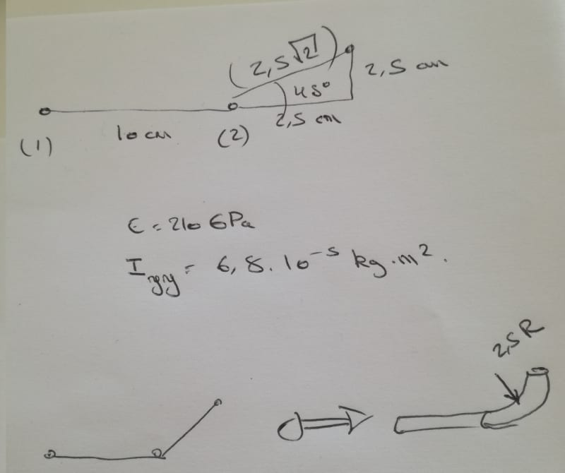
However, when I do the numerical analysis I get a global stiffness matrix which determinant is equal to 0. Here's the numerical analysis below.

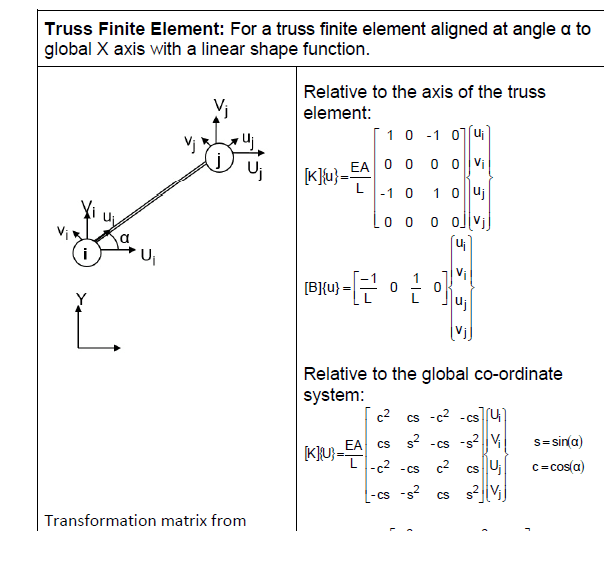
To find the global stiffness matrix, I used the formula below.

So when I modelled everything on abaqus, I got some decent results. However, my numerical analysis doesn't work.
I thought about using a beam element.
Would you have any ideas ?
thanks a lot for your time.
Along my new professional career, I'm working in FEA and I've been training by modelling some simple stuff and more complex ones.
This one is a bit tricky since I've tried to create a simple model of a hanger for lifting slings (you can see its picture below).

As you can see, it seems like there's a shaft of roughly 100 mm long and an arc supposed to be 25mm radius. This is the hypothesis I went with.
However, when I do the numerical analysis I get a global stiffness matrix which determinant is equal to 0. Here's the numerical analysis below.

To find the global stiffness matrix, I used the formula below.

So when I modelled everything on abaqus, I got some decent results. However, my numerical analysis doesn't work.
I thought about using a beam element.
Would you have any ideas ?
thanks a lot for your time.
