Continue to Site

Eng-Tips is the largest engineering community on the Internet

Intelligent Work Forums for Engineering Professionals

  • Congratulations SSS148 on being selected by the Eng-Tips community for having the most helpful posts in the forums last week. Way to Go!

Modelling of a Timber Roof

Status
Not open for further replies.

kellez

Civil/Environmental
Nov 5, 2011
276
Hello everyone,

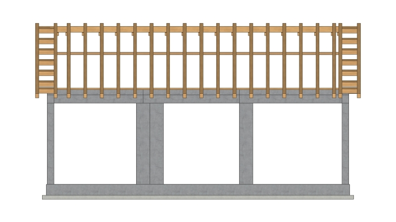
I am designing a timber roof supported on an RC slab (which many of you have already seen). After a lot of help from members of the forum i have come up with the design shown at the bottom of the post.

I am now modelling the timber roof frame for the analysis and design and i need your advice on what supports/type of joints shall i use between the members.

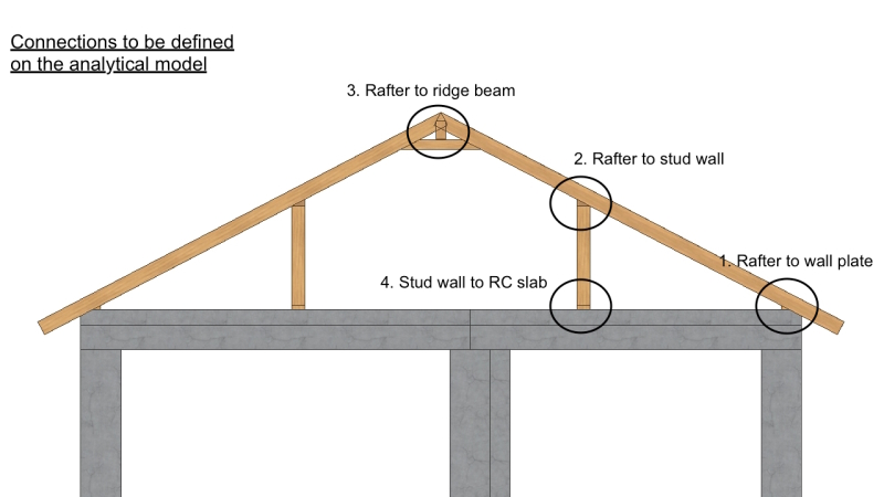
In total there are 4 different connections that i need to model

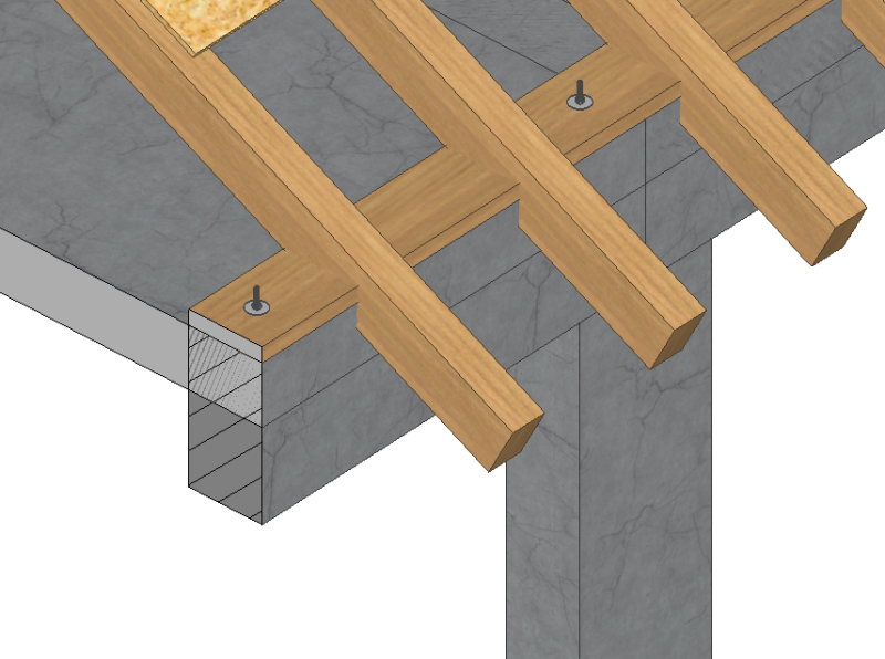
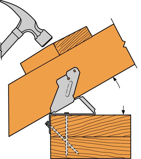
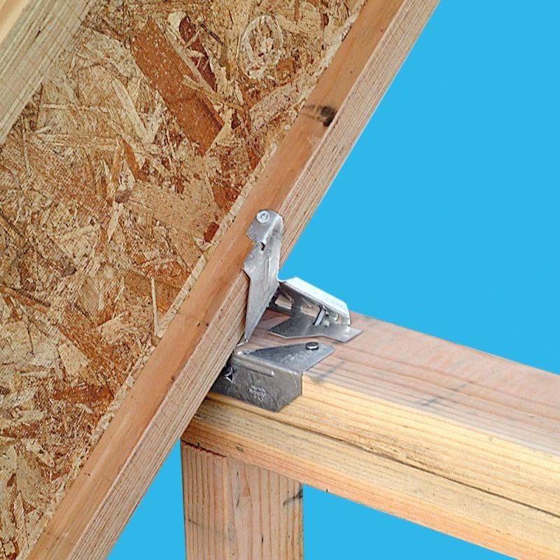
1) Rafter to wall plate
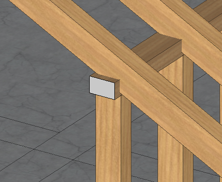
2) Rafter to stud wall
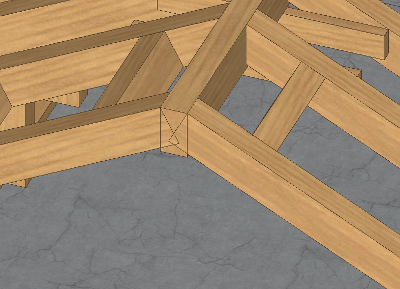
3) Rafter to ridge beam at the top
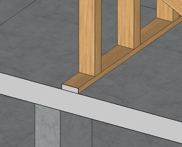
4( Stud wall to concrete slab

MONASTIRI_-_Final_Roof_Design_4_2_zrz4s1.jpg


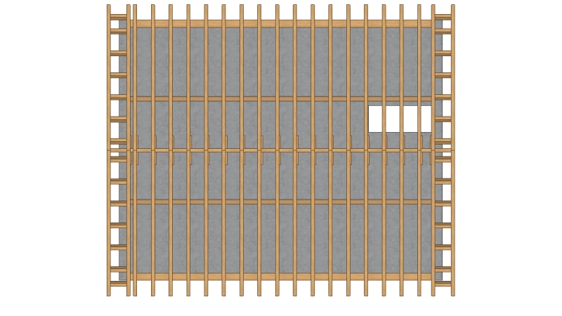
I am modelling the whole structure together including the RC Columns, beams and slabs together with the timber roof.


MONASTIRI_-_Final_Roof_Design_4_2_copy_2_ebwvao.jpg


Final design of the roof

MONASTIRI_v10_-_Structural_Model_-_33_-_Timber_Roof_Design_3_ScreenShot_24102017_184822_pfp9hw.jpg


MONASTIRI_v10_-_Structural_Model_-_33_-_Timber_Roof_Design_3_ScreenShot_24102017_184149_fawsn5.jpg


MONASTIRI_v10_-_Structural_Model_-_33_-_Timber_Roof_Design_3_ScreenShot_24102017_190214_wxpevi.jpg


MONASTIRI_v10_-_Structural_Model_-_33_-_Timber_Roof_Design_3_ScreenShot_24102017_185444_lv8unj.jpg


MONASTIRI_-_Final_Roof_Design_9_opim0f.jpg


MONASTIRI_-_Final_Roof_Design_8_ckxxcm.jpg
 
Replies continue below

Recommended for you

Loads, trib. areas, simple span beams/columns, load path, reactions, connection selection, repeat....If anything your drawings are very nice!
 
1. Rafter to wall plate: There should be a sill board (2x) above the concrete attached similar to item 4. The rafter gets notched around it. Also, the overhangs get squared off.
2. Rafter to stud wall: Do not notch. Use simpson connector or 2x stub.
3. Rafter to ridge beam: cut rafters vertical. ridge beam is continuous.
4. Stud wall to slab: Expansion/wedge/mechanical anchors or concrete screws.

Wood rafter roofs are very common. It might be best to put vague notes for code compliance.

Also, this looks difficult to insulate
 
RPMG said:
1. Rafter to wall plate: There should be a sill board (2x) above the concrete attached similar to item 4. The rafter gets notched around it. Also, the overhangs get squared off.
2. Rafter to stud wall: Do not notch. Use simpson connector or 2x stub.
3. Rafter to ridge beam: cut rafters vertical. ridge beam is continuous.
4. Stud wall to slab: Expansion/wedge/mechanical anchors or concrete screws.

Wood rafter roofs are very common. It might be best to put vague notes for code compliance.

Also, this looks difficult to insulate

Thanks a lot for your reply, taking your advice into consideration these are the connections I have.

What about the joints in the analytical model?

1. Rafter to wall plate -> birdsmouth cut on rafter connected to wall plate with screws and L-shaped brackets on both sides
What joint shall I use for the analytical model? PINNED or FIXED or what releases shall i apply?

Screen_Shot_2017-11-01_at_00.13.50_hhhufd.png


2. Rafter to stud wall -> birdsmouth cut on rafter or SIMPSON VPA connector without the cut
What joint shall I use for the analytical model? PINNED or FIXED or what releases shall i apply?

Screen_Shot_2017-11-01_at_09.45.06_m02lxt.png


3. Rafter to ridge beam -> cut rafters vertical, connect to ridge beam with screws. ridge beam is continuous.
What joint shall I use for the analytical model? PINNED or FIXED or what releases shall i apply?

Screen_Shot_2017-11-14_at_09.35.53_oo6lnh.png


4. Stud wall to slab -> Connect to RC slab with SIMPSON anchoring bolts
What joint shall I use for the analytical model? PINNED or FIXED or what releases shall i apply?

Screen_Shot_2017-11-01_at_09.54.17_unb3dd.png
 
[quote
kmart30]Loads, trib. areas, simple span beams/columns, load path, reactions, connection selection, repeat....If anything your drawings are very nice![/quote]

Thank you, however I did not quite get the concept of your reply, I do know how to model and carry out an analysis...However i did not get the REPEAT part, in order to repeat the analysis i need to change something, what shall i change before I repeat? the connection type i guess? but how would i know which connection is the correct one, i do not have a real life model to compare to, or experimental results.

What shall i expect to see in my results in order to decide on the best connection type?
 
For the analysis side of things. All pins. Generating fixity in wood-wood connections requires tight detailing and lots of fasteners. That is not generally required for structures like these.

Also as mentioned in the previous thread, your birdsmouth cut at the bottom of your rafters seems excessive. As dik noted, it's typically limited to 1/3 of the member depth.
 
jayrod12 said:
For the analysis side of things. All pins. Generating fixity in wood-wood connections requires tight detailing and lots of fasteners. That is not generally required for structures like these.

Also as mentioned in the previous thread, your birdsmouth cut at the bottom of your rafters seems excessive. As dik noted, it's typically limited to 1/3 of the member depth.

Thanks a lot thats great i will use all pins for the joints. Indeed the birdsmouth cut is excessive, I am changing that, that is not the final design.
 
My comment for item 2 was misinterpreted. Do not cut a birdsmouth. That is a notch at a neg moment high point.

The top plate can be at roof slope, studs extend to rafter with blocking, or metal connector. There are lots of options.
 
RPMG said:
My comment for item 2 was misinterpreted. Do not cut a birdsmouth. That is a notch at a neg moment high point.

The top plate can be at roof slope, studs extend to rafter with blocking, or metal connector. There are lots of options.

Yes of course you are right, we do not want to weaken the rafter at that specific point, as you said that is where the max bending moment is expected.

Therefore my options for the Rafter to Stud wall connection are:
1) use 2x top plates on the stud wall and bevel the top plate at the roof angle for the rafter to sit on WITHOUT a birdsmouth cut
or
2) use a SIMPSON VPA connector as shown below

vpa-situation-clouage-2-2-jpg_xy9ya5.jpg


simpson-strong-tie-construction-connectors-vpa2-4f_1000_d4l9ow.jpg
 
Status
Not open for further replies.

Part and Inventory Search

Sponsor