Continue to Site

Eng-Tips is the largest engineering community on the Internet

Intelligent Work Forums for Engineering Professionals

  • Congratulations waross on being selected by the Eng-Tips community for having the most helpful posts in the forums last week. Way to Go!

Modelling of transformer and MV cable for harmonic studies

Status
Not open for further replies.

Waqasakbar323

Electrical
Apr 28, 2022
3
For my research project, modelling is needed for dyn5 630 kVA transformer and 20 kV cable NA2XS(F)2Y to do harmonic analysis. For that i need leakage reactance, and resistance of copper losses for transformer. And following parameters for 20 kV cable are also needed.

Positive, negative and zero sequence of resistance, reactance and susceptance.

Can anyone help in it?
 
Replies continue below

Recommended for you

Following IEC 60076-5 and manufacturer data for power transformer with 2 windings-high and low voltage the minimum short-circuit voltage for 630 kVA it is 4%.However most of dry type transformers present 6%. The copper losses from are 5000 to 6000 W then the X/R it is approximate 5.
In these conditions Z=27 to 32 ohm [from 20 kV side ] then X=26.5 to 31 and R=5.2 to 6.2 ohm.
The cable NA2XS(F)2Y 20 kV according to IEC 60502-2, IEC 60228 and manufacturer catalogue r[ac.90oC]=1.13 ohm/km ; x[50 Hz]=0.1455 ohm/km trefoil or 0.2036 ohm/km flat
 
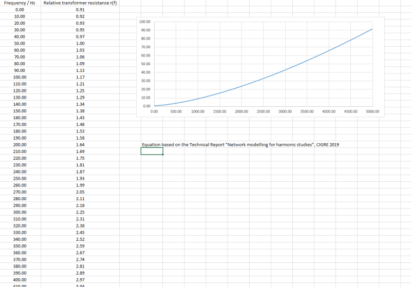
Thanks for your reply. Do you have idea how transformer is modelled for simulation for harmonic studies? What i found is, series leakage inductance and copper losses are mainly frequency dependent. SO to model it, one can get these parameters from manufacturer. It should be in tabulated form as sample shown.But unfortunately, the manufacturer of transformer in our lab has not performed frequency analysis on this transformer. Now my supervisor says, to get these leakage inductance and copper losses based on frequency scale from any other source (literature, simulation software developers, open forums or any other manufacturers). That is why i am using this forum. But the parameters you mentioned does not seem like a frequency scale characteristics of transformer. What is your comments? Maybe our discussion can give my work a favourable direction. Thanks

Sample-FREQUENCY_SCALE_CHARACTERISTICS_OF_TRANSFORMER_hfcilq.png
 
Waqasakbar Resistance is not frequency dependent, although inductance and capacitance are. Since total impedance is a function of the R-L-C circuit connection, it follows that the IMPEDANCE is also frequency dependent. Your table is therefore for IMPEDANCE, not resistance.

I suspect Zanoter's response is for a single frequency point (typically line frequency). Use the mathematical relationship for calculating inductance (and/or capacitance) for the line frequency condition to get the non-frequency components based on Zanoter's estimates. Then plug in the frequencies of interest to obtain your "predicted" curve.

Converting energy to motion for more than half a century
 
It is very interesting indeed. However, for cables the system frequency influence calculating it is simpler considering only skin effect and proximity effect as per IEC 60287[ or according to Neher and McGrath or even IEEE 835] for resistance. For cable other parameters you may follow the attached file.
If we should transfer the theory in transformer case, we don't know the conductor details in such a way to calculate nor skin neither proximity effect. There are a lot of publications connected with but most of them are for cable usually.
 
 https://files.engineering.com/getfile.aspx?folder=93563f0f-490e-436b-8a5f-b08428b04be2&file=Sequence_impedances.pdf
Status
Not open for further replies.

Part and Inventory Search

Sponsor