Eng-Tips is the largest engineering community on the Internet

Intelligent Work Forums for Engineering Professionals

  • Congratulations waross on being selected by the Tek-Tips community for having the most helpful posts in the forums last week. Way to Go!

modelling surface contact with large gaps in between ? 1

Status
Not open for further replies.

prakhar5aug

Automotive
Jul 19, 2014
28
0
0
FR
Hello,
I am modelling a simple structure with two sheets which are about 20mm apart both are fixed, force is applied on the lower sheet in upward direction such that it bends and then touches the upper sheet....
I have applied both surface to surface contact mesh from FEM environment and surface contact from SIM environment but in both cases before lower sheet is bended just half the distance (8-12mm) the upper sheet starts to bend.... i.e. they are apart but still they behave as if touched....
and if does not apply anything the sheet just pass through each other....is there any waw to tell NX that there is sheet do not cross it....

Kindly suggest some ways to model the same...

Thanks & Regards,
Prakhar Gupta
 
Replies continue below

Recommended for you

Hello!,
Use one method or another, but not both at the same time. Surface-to-Surface contact in the SIM file will run only in Linear Static Analysis (SOl101). Do not forget to enter the search distance > 20 mm in order to the contact to run properly.

CGAP contact elements node-to-node defined in the FEM environment runs in both linear static (SOL101) and nonlinear analysis (SOL106). If both parts are touching, then GAP distance property should be zero. Also in the EDIT MESH ASSOCIATED DATA you should have to define the value of compression stiffness, for instance 1E6 is correct, this means the CGAP elements will run at compression only, OK?.

Also you should EDIT the study properties and activate "TREAT CGAP AS LINEAR CONTACT ELEMENT", if not the CGAP element will run as an spring.

Best regards,
Blas.

~~~~~~~~~~~~~~~~~~~~~~
Blas Molero Hidalgo
Ingeniero Industrial
Director

IBERISA
48004 BILBAO (SPAIN)
WEB: Blog de FEMAP & NX Nastran:
 
Hi
Thanks for detailed reply.
I have applied one method at a time only.
In sim environment I have applied min dist. = 18 & max dist = 23 but then also as soon as lower sheet starts to bend the upper sheet is also affected without even touching it.

In fem I was missing to edit treat cgap as contact element but after changing it, it maded all the contacts incative while solving and sheet just pass through each other.....

Is cgap and pgap element different because when i applied surface contact the element created was pgap not cgap

Can you explain it in more detail....

Thanks & Regards
Prakhar Gupta
 
Gap properries
Initial opening 18 mm
Axial stiffness closed gap 1500000 N/mm
Axial stiffness open gap 10 N/mm
Transverae stiffness gap closed 150000 N/mm
Coeff friction Y 0.3
 
Dear Prakhar,
In the FEM is where you define the PGAP properties like INITIAL GAP OPENING and AXIAL STIFFNESS FOR OPEN GAP, these are the most important values. Also in the EDIT MESH ASSOCIATED DATA you need to define the orientation of the CGAP elements, this is critical when dealing with node-to-node CGAP contact elements.

For instance, here you are a simply LINEAR constact between two cantilever plates using CGAP elements to define "explicitely" node-by-node the contact between both plates. The good message is that this problem can be solved both linear & nonlinear accounting for large displacements effects, contact and material nonlinearities (SOL106), OK?.

cgap-contact.png


The following picture shows the displacements results, please note the deformed shape is exagerated, this is a linear static analysis!!.

cgap-results.png


The surface-to-surface contact definition in the SIM file is more easy-to-use, not need to mesh "explicitely" any contact element, is the modern technology, in general more accurate than CGAP elements. Then define a simply problem to understand how it runs and sure you will arrive to reliable results. But please note that surface-to-surface contact NO PENETRATION is only linear contact, runs only with linear static (SOL101).

Best regards,
Blas.

~~~~~~~~~~~~~~~~~~~~~~
Blas Molero Hidalgo
Ingeniero Industrial
Director

IBERISA
48004 BILBAO (SPAIN)
WEB: Blog de FEMAP & NX Nastran:
 
Hello,

Same problem persist can you help in FEM method more details about the INITIAL GAP OPENING & AXIAL STIFFNESS FOR OPEN GAP, and also about the orientation of element.

Thanks & Regards,
Prakhar Gupta
 
Dear Prakhar,
Please note in advance that this problem ONLY arrives to reliable solution if you perform NON LINEAR ANALYSIS + LARGE DISPLACEMENT EFFECTS, using linear contact between two plates of thickness 2 mm separated with a distance of 28mm is not possible to arrive to a valid solution, this is useless, OK?. The problem could be solved if you move the plates till touching each other (gap separation = 0 mm) and then perform the linear contact analysis, then we are in the range of small displacements, valid for linear static SOL101 solutions, OK?.

Regarding the problem posed here, I see error in the orintation of CGAP elements, never use a vector in the axial direction of CGAP element, but transverse to CGAP element. Also I edited the CGAP distance to 28 mm, not 25mm. And solved the problem. Apparently all ran OK, but iterations of contact convergence do not reach equilibrium because 20 iterations were consumed, and the limit (by default) is 20. The NX NASTRAN solver stop the solution without giving any error message, and this is dangerous because users beleive that everything was OK. But if you inspect the *.F06 file you will see the problem:

Code:
 ^^^CONTACT ITERATION NUMBER        20 
 ^^^     
 ^^^NUMBER OF CONTACT STATUS CHANGES:                0       (NCHG:            0)    
 ^^^NUMBER OF INACTIVE CONTACTS:                   249 
 ^^^NUMBER OF STICKING CONTACTS:                     1 
 ^^^NUMBER OF SLIDING CONTACTS:                      0 
 ^^^      FORCE LOOP:            1 
 ^^^      FORCE LOOP:            2 
 ^^^      FORCE LOOP:            3 
 ^^^      FORCE LOOP:            4 
 ^^^      FORCE LOOP:            5 
 ^^^      FORCE LOOP:            6 
 ^^^      FORCE LOOP:            7 
 ^^^      FORCE LOOP:            8 
 ^^^      FORCE LOOP:            9 
 ^^^      FORCE LOOP:           10 
 ^^^CONTACT FORCE CONVERGENCE RATIO:      1.055480E-02       (CTOL:     0.000000E+00)    
 ^^^     
 ^^^     
 ^^^     
 ^^^NUMBER OF CONTACT STATUS CHANGES:                0       (NCHG:            0)    
 ^^^NUMBER OF INACTIVE CONTACTS:                   249 
 ^^^NUMBER OF STICKING CONTACTS:                     1 
 ^^^NUMBER OF SLIDING CONTACTS:                      0 
 ^^^      FORCE LOOP:            1 
 ^^^      FORCE LOOP:            2 
 ^^^      FORCE LOOP:            3 
 ^^^      FORCE LOOP:            4 
 ^^^      FORCE LOOP:            5 
 ^^^      FORCE LOOP:            6 
 ^^^CONTACT FORCE CONVERGENCE RATIO:      9.924633E-03       (CTOL:     0.000000E+00)    
 ^^^ USER WARNING MESSAGE 9284 (PHASE1D) 
 ^^^ [b][COLOR=#EF2929]NUMBER OF OUTER LOOP ITERATIONS EXCEEDED[/color][/b]    
1

contact-reach-20-iterations.png


This means that the last contact iteration is reached without convergence. Hence, the deformed shape is not the right one expected.
Top workaround this issue, one can set a connection property so that a BCTPARM card can be written in your nastran deck file using a MAXIMUM STATUS ITERATIONS (MAXS) of 40 iterations (take a look to the NX NASTRAN manual for BCTPARM command!!).

BCTPARM 100 PENN 10. PENT 1. MAXF 20 +
+ MAXS 40 CTOL 0.01 NCHG 0.02 MPER +
+ REFINE 0


In fact, entering the above parameters in the BULK DATA the solution runs with success:

Code:
 ^^^CONTACT ITERATION NUMBER        16 
 ^^^     
 ^^^NUMBER OF CONTACT STATUS CHANGES:                0       (NCHG:            0)    
 ^^^NUMBER OF INACTIVE CONTACTS:                   249 
 ^^^NUMBER OF STICKING CONTACTS:                     1 
 ^^^NUMBER OF SLIDING CONTACTS:                      0 
 ^^^      FORCE LOOP:            1 
 ^^^      FORCE LOOP:            2 
 ^^^      FORCE LOOP:            3 
 ^^^      FORCE LOOP:            4 
 ^^^      FORCE LOOP:            5 
 ^^^      FORCE LOOP:            6 
 ^^^      FORCE LOOP:            7 
 ^^^      FORCE LOOP:            8 
 ^^^      FORCE LOOP:            9 
 ^^^      FORCE LOOP:           10 
 ^^^      FORCE LOOP:           11 
 ^^^      FORCE LOOP:           12 
 ^^^      FORCE LOOP:           13 
 ^^^      FORCE LOOP:           14 
 ^^^      FORCE LOOP:           15 
 ^^^      FORCE LOOP:           16 
 ^^^      FORCE LOOP:           17 
 ^^^      FORCE LOOP:           18 
 ^^^      FORCE LOOP:           19 
 ^^^CONTACT FORCE CONVERGENCE RATIO:      9.946236E-03       (CTOL:     1.000000E-02)    
 ^^^     
 ^^^     
 ^^^FINAL CONTACT STATUS AT CONVERGENCE  
 ^^^     
 ^^^NUMBER OF CONTACT STATUS CHANGES:                0       (NCHG:            0)    
 ^^^NUMBER OF INACTIVE CONTACTS:                   249 
 ^^^NUMBER OF STICKING CONTACTS:                     1 
 ^^^NUMBER OF SLIDING CONTACTS:                      0 
 ^^^     
 ^^^[b]CONTACT ITERATION CONVERGED[/b]

And you can plot "meaningless" results of linear contact displacement using a scale factor of 1:1,

displacement-results.png


Best regards,
Blas.

~~~~~~~~~~~~~~~~~~~~~~
Blas Molero Hidalgo
Ingeniero Industrial
Director

IBERISA
48004 BILBAO (SPAIN)
WEB: Blog de FEMAP & NX Nastran:
 
Dear Blas,
Thanks a lot for the detailed explaination...
Few Querries
1. Result is meaningless as you say it is linear analysis and possible solution is to reduce the distance between them to 0 and then solve but my doubt is then, will it include the effect of initial bending and energy lost in it?? (I think then result will be correct but problem will be changed)

2. As in my problem sheets are large distance apart,so to get reliable solution I need to perform NON LINEAR ANALYSIS + LARGE DISPLACEMENT EFFECTS, can you elaborate more on considering large displacement effect ??

Thanks & Regards,
Prakhar Gupta
 
Dear Prakhar,
If the real problem is like you describe, then the only valid method to arrive to a reliable solution is to run the NX NASTRAN BASIC NONLINEAR module (SOL106), activating -by default- the large displacement effect (PARAM,LGDISP,1). The CGAP element is a nonlinear element that will perform the contact iterations perfectly. Also, because you are solving a nonlinear analysis you can play with material nonlineatities if required.

Best regards,
Blas.

~~~~~~~~~~~~~~~~~~~~~~
Blas Molero Hidalgo
Ingeniero Industrial
Director

IBERISA
48004 BILBAO (SPAIN)
WEB: Blog de FEMAP & NX Nastran:
 
Dear Prakhar,
In nonlinear analysis things are not so easy as in linear one, mesh quality is critical to arrive to a convergence solution, also you need to read NX NASTRAN manuals to understabd the nonlinear parameters, I strongly suggest to contact sur SIEMENS VAR RESELLER to ask for NX AdvSim CAE training, this forum only can provide some tips & tricks, but with alimited path.

To start with, for nonlinear analysis you may define the simplest model as possible: for instance, I note the material has defined a stress-strain relationship, then the solver will account for material nonlinearities when running the analysis. Change the material to not consider any material nonlinerarity in the first analysis. If the problem solve with success, that revise results and add material nonlinear model if required and repeat the analysis.

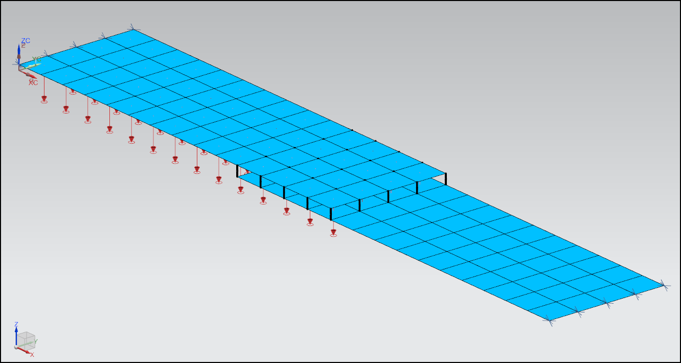
Also, revising the mesh I note that RBE3 RIGID elements are included in the FEM model!. In fact, "surface-Contact-mesh" based in node-yo-node CGAP elements is tricky in NX ADVSIM, if the two end nodes of the CGAP elements are not exactly coincident and alligned then NX AdvSim will create in one end a spider based in RBE3 elements to "solve" the problem. If I open the model in FEMAP you can see the spiders used based in RBE3 elements (in white color).

fe-model.png


This is a problem because rigid elements for nonlinear analysis are of not good for the NX NASTRAN solver, is not reconmended at all, then in the future make sure that both nodes of the CGAP element are perfectly aligned, ie, the mesh in top and bottom plates in contact should be exactly coincident to avoid the creation of rigid elements. Simply make an imprint of the top edges in the bottom surface and you are done, this way the mesh in both plates will be identical. According the NX NASTRAN BASIC NONLINEAR ANALYSIS GUIDE "Rigid body elements (RBEi, RBAR, RROD entries, etc.) do not rotate in geometric nonlinear analysis", then its use should be avoided as much as possible.

Also, one limitation for CGAP node-to-node in nonlinear analysis is that one of the contact surfaces should not rotate by a large angle because the gap element orientation is not updated for large rotations. If large rotation exsit, then the ADVANCED NONLINEAR MODULE is recomended where the full "surface-to-surface contact" is supported, not need to use 1-D node-to-node contact, OK?.

And finally, the CGAP properties (the PGAP card) at the beginning should be as simply as possible, avoid the use of friction, this will add complexity to the convergence, start without friction.
Regarding nonlinear parameters (NLPARM card) start with 50 increments using the stiffness update strategy = ITER method and Number of iterations before the stiffness update = 1.

pgap-props.png
_
nlparm.png


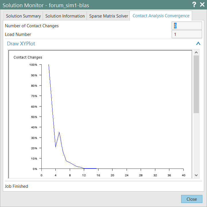
Run the nonlinear static analysis (SOL106) and the convergence will be reached in 184 iterations:

nonlin-iterations.png


Plot the displacements and stress results AT EVERY STEP and compare with the linear static analysis (SOL101), now you will understad why linear static results are meaningless when geometric nonlinear large displacements effects are involved. Here you are attached the NX NASTRAN *.dat input file.

nonlin-ures-nx-animated.gif


Best regards,
Blas.

~~~~~~~~~~~~~~~~~~~~~~
Blas Molero Hidalgo
Ingeniero Industrial
Director

IBERISA
48004 BILBAO (SPAIN)
WEB: Blog de FEMAP & NX Nastran:
 
Hello Blas,

Thanks for the detailed reply which helped me in understanding the non - linear analysis and the behaviour of certain elements in SOL 106.

I was able to model the same and got fairly better results.

few queries

1. It suddenly jumps in between what is that jump? and at the same time stress starts to transfer to the upper sheet, is it the contact between the two.
2. There is still gap between the sheet when stress starts to transfer is it due to the sheet thickness? because I want to Animate it as touching.

looking forward for the "SIEMENS VAR RESELLER to ask for NX AdvSim CAE training".

Thanks & Regards,
Prakhar Gupta
 
Dear Prakhar,
1.- It seems that a buckling exist in the response, then the "default" load control method failed to capture the intermediate steps in the solution and the plate snaps to the next loading step changing from compression to tension. To capture this behaviour you need to change the control method to either increase displacements or "arc-length" Risk method, this way the NX NASTRAN solver do not increment the load but the length of the equilibrium curve path.
2.- Initial open GAP distance must account for the shell thickness, is crtical to mesh with the CGAP element "normal" to both plates to account correctly for the open gap distance. If you have different initial GAP oppening the you must define different PGAP properties.

Best regards,
Blas.

~~~~~~~~~~~~~~~~~~~~~~
Blas Molero Hidalgo
Ingeniero Industrial
Director

IBERISA
48004 BILBAO (SPAIN)
WEB: Blog de FEMAP & NX Nastran:
 
Status
Not open for further replies.
Back
Top