Eng-Tips is the largest engineering community on the Internet

Intelligent Work Forums for Engineering Professionals

  • Congratulations waross on being selected by the Tek-Tips community for having the most helpful posts in the forums last week. Way to Go!

Modelling walls that don't line up in Etabs 2

Status
Not open for further replies.

dsdt

Structural
Jan 18, 2021
14
0
0
AU
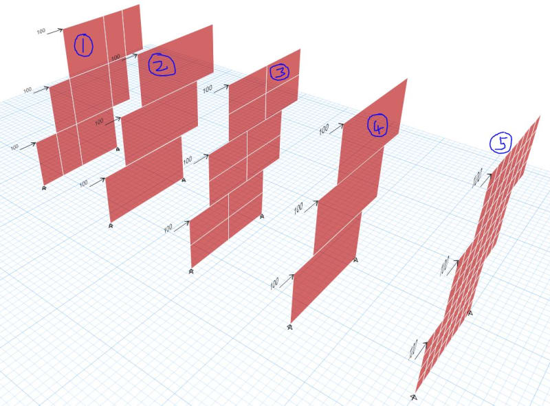
Just wondering how you guys model walls that don't line up in 3D FE model like ETABS?
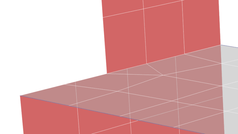
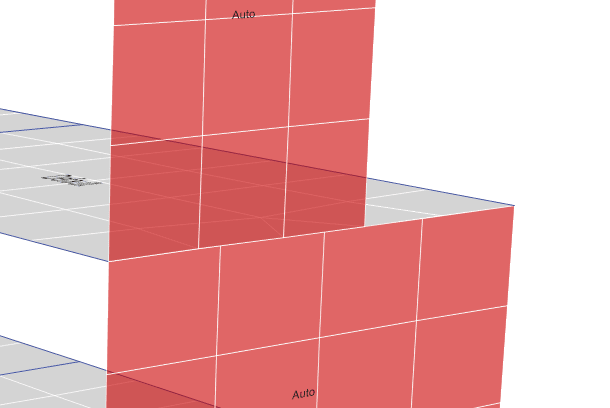
See below as an example. As you can see, the meshes that don't line up. And the slab meshes just match above. So, how do you normally separate the walls below into two or do you prefer manual meshing?
mesh0_pyitzm.png

mesh1_ktghxl.png
 
Replies continue below

Recommended for you

The reason I am reluctant to divide the wall shell into multiple pieces is it will create too many wall panels in the model.
I know there is a auto edge constraints option in ETABS. Do you recommend use this function but not divide the wall shells?
 
So just model as one wall above and one wall below with normal meshing, no need to divide shells into smaller pieces as long as auto edge constraints are assigned? I thought even if edge constraints are assigned we still needs to divide shells?
 
I don't believe there is any need to divide the shells. You can always check the deflected shape to ensure the edge constraint has been applied correctly.
 
I'm not convinced that Auto Edge Constraints produces the same results as a cleanly meshed wall.

I think ETABS wall auto-meshing needs some work.
 
If you want to test the accuracy of this mesh (which is relying heavily on the edge constraints) then keep a couple of parallel copies of the model where you test the different mesh options and compare the results.

Personally, I don't like it when my floor to floor mesh is less than 4 plates wide or 3 plates tall. I'm probably a little more trusting of the edge constraints than some. But, it makes perfect sense to test it out before you rely on that feature.

Caveat: I work for CSI (the maker of ETABS), though I'm still learning the intricacies of the programs. So, take my comments with whatever personal bias that may give me. Lastly, I contribute to Eng-tips for my personal benefit, not as a representative of the company. So, don't take what I say as gospel.... There are a lot of technical details of the program (like edge constraints) about which I'm not fully knowledgeable yet.
 
The slab general automesher is now smart enough to grab all joints presented within the slab shell and around the edge.

For example, you don't need to manually mesh the slab for a transfer column, it will automatically make the column base joint a mesh seed point.

Unfortunately, the same can't be said for the wall automesher. You need to manually mesh vertically at steps within the wall, wall intersections. In addition you need to manually mesh horizontally at door openings right around the core. Which then makes it a real pain to edit door opening setting out once you've gone down the manual mesh rabbit hole.

While I'm at it... a void shell element similar to what you can use for slabs would be a godsend for walls. Again, it would make it much simpler to shift the void shell element.
 
Can you please elaborate on this a bit more? I had a quick look on the introduction of "auto edge constraints" (link Looks like master/slave nodes will be created only at shell ends, in which case reducing the size of the meshes don't seem to lead to a more accurate results since these node don't line up vertically and they are not master nodes? However, dividing shells into smaller pieces will create more master joints, leading to a more accurate result?

Noted. Thank you for your help.
 
Does Etabs support 'general' meshes other than 'rectangular' for walls? I believe it support rectangular only, in which case it is hard to manually mesh to let them line up. What I tent to do it break the wall below into two panel at intersection, which I find it onerous sometimes.
 
If you select a walls, then use Assign - Shell - Wall Automesh Options, then you can set different mesh constraints. You've got a number of options:

a) Mesh Object into __ vertical and ___ horizontal: You can use this option to force a wall to have the exact mesh (rectangular) that you want. You might have to over mesh to get it to match up with the wall above and below. But, you've got a lot of control.

b) Auto-Rectangular Mesh (but using the Advanced - Modify Settings): You can use the advanced setting to force the automesh to use an approximate maximum mesh size.

c) A true manual mesh. Meaning you input the shells manually so that everything matches up. This would NOT be done through these Wall Automesh Options.

Set up 3 or more models with identical lateral load applied to them. Solve each model and compare the results. See what the total deflections are, whether you see any "separation" at the misaligned mesh locations...etc.

I know this is a pain in the rear. A lot of work to do for a single feature. But, it's the best way to really, truly get comfortable with a feature, what it's doing and how to use it properly.

Note: You can do similar things with the Assign - Shell - Floor Automesh Options to check to see how the floor meshes and how the forces transfer between floor and wall.


Few different options below. All have Auto Edge Constraints.

1 - course but correct manual mesh with all joints noded out
2 - no meshing whatsoever
3 - finer mesh but not noded out correctly. This would rely on AEC.
4 - Automesh to 1m element size
5 - Manually meshed to 1m element size

Notes:

- I don't like that the program will show literal airgaps for deformed shapes when relying on mesh that isn't noded out and Auto Edge Constraints.
- I don't like the discontinuous stress diagrams you get with poorly manual meshed walls and AEC.
- There is over 30% increase in deflection with a fine mesh as opposed to no meshing at all.

WALLS_d36f5h.jpg


Deflection

HORZ_DEFLECTION_td1zrz.jpg


Vertical Stress

VERT_STRESS_yzg0ls.jpg
 
Status
Not open for further replies.
Back
Top