NeodymiumSnail
Electrical
One of the best perks of being an electrical PE at MEP firms was having constant access to advice from architects and other engineers, for both work-related and personal projects. I'm no longer in contact with any of my former coworkers so I'm hoping someone here can advise me on what I think is a simple change to a proven design.
The DIY laminar flow hood creates a small, sterile space using a 0.3 micron filter. The performance of the specified filter/fan combo was proven using a Met One GT-521 laser particle counter and smoke. I saw video of the test and the counter read zero throughout the work space, which is surprising given the price and appearance of the hood.
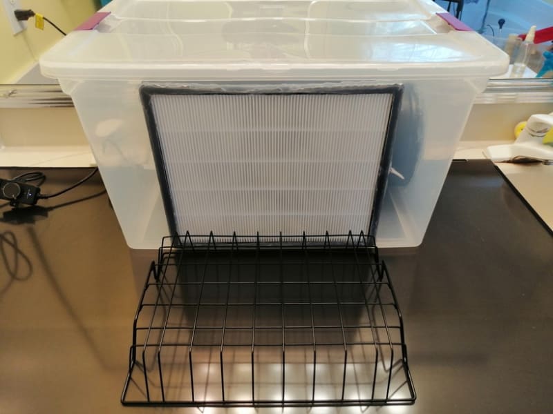
It's built in a plastic tote with the fan inside blowing out thru the filter. Here is a photo:

*AC Infinity Raxial S6 variable speed fan: Not intended for static pressure applications. Air blows both directions at the intake but it works anyway. $35
*Levoit LV-PUR131 Air Purifier filter: generic is fine but it has to be one of the ones that was tested with the particle counter because the market is full of under-performing "fakes"
*the rack is there to elevate the work above the turbulent flow at the bottom edge of the filter
The inline style fan discharges perpendicularly to the direction of flow thru the filter, with its output roughly a few inches behind and below the center of the tote. The sterile work space is an area about 2" in from the edges of the filter and about 7" out in front. The fan speed must be set using smoke or a flame to ensure laminar flow.
Others have successfully modified the design so the fan is on top blowing downwards. It's known that putting the fan on the back, blowing forwards, doesn't work because it creates uneven pressure on the filter.
I need a more compact version, using the same cheap filter and fan. Instead of the tote I have a section of salvaged 12x5" rectangular duct. The filter is 11.4" x 13.4" so it will fit perfectly with a piece of that duct turned on it's side. I'll use a 6" round duct take-off and a support bracket to mount the fan outside the duct, next to the work space and blowing backwards relative to the filter flow.
The filter needs even pressure to produce laminar flow. Based on mechanical engineering discussions I overheard during my years of work I suspect the space in the tote could be considered a plenum, and that plenums need to be properly sized to produce even pressure. I don't know how to do that but I've gathered some basic info below.
Original tote "plenum" volume calculation:
66 quart tote - (7.3" long x 6" dia fan) =
2.2 cubic feet - 0.1 cubic feet = 2.1 cubic feet
Minimum possible "plenum" volume using 12x5" duct:
min length = 13.4"(filter) + 1/4"x2(for caulking seal) + 8"(flange dia for 6" take-off) = about 22"
22" x 5" x 12"= 0.76 cubic feet
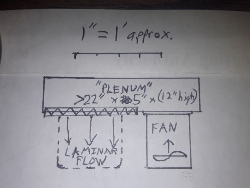
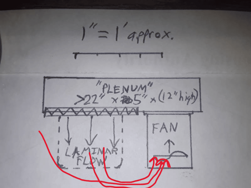
Sketch of proposed compact hood in plan view:

The filter and fan would fit on a 22" piece of duct but it may need to be longer so there's more clearance between the work space and the fan, or to get a larger volume "plenum."
I read that the higher the flow the bigger a plenum needs to be to have even pressure. According to the original designer this filter needs about 200-250 CFM. He studied the laminar-turbulent transition and Reynold's number, which is all over my head.
How do I calculate the minimum plenum volume for a given flow rate?
What are the design guidelines regarding plenum geometry?
If I'm on the wrong track and these calculations aren't necessary that would be really helpful to know too.
I'm also concerned the fan's intake could alter airflow in the work space. It's easy enough to change later but do you think I'll need a 90 degree bend and/or short piece of round duct to prevent that?
Any advice will be appreciated, and thanks for reading all this!
The DIY laminar flow hood creates a small, sterile space using a 0.3 micron filter. The performance of the specified filter/fan combo was proven using a Met One GT-521 laser particle counter and smoke. I saw video of the test and the counter read zero throughout the work space, which is surprising given the price and appearance of the hood.
It's built in a plastic tote with the fan inside blowing out thru the filter. Here is a photo:

*AC Infinity Raxial S6 variable speed fan: Not intended for static pressure applications. Air blows both directions at the intake but it works anyway. $35
*Levoit LV-PUR131 Air Purifier filter: generic is fine but it has to be one of the ones that was tested with the particle counter because the market is full of under-performing "fakes"
*the rack is there to elevate the work above the turbulent flow at the bottom edge of the filter
The inline style fan discharges perpendicularly to the direction of flow thru the filter, with its output roughly a few inches behind and below the center of the tote. The sterile work space is an area about 2" in from the edges of the filter and about 7" out in front. The fan speed must be set using smoke or a flame to ensure laminar flow.
Others have successfully modified the design so the fan is on top blowing downwards. It's known that putting the fan on the back, blowing forwards, doesn't work because it creates uneven pressure on the filter.
I need a more compact version, using the same cheap filter and fan. Instead of the tote I have a section of salvaged 12x5" rectangular duct. The filter is 11.4" x 13.4" so it will fit perfectly with a piece of that duct turned on it's side. I'll use a 6" round duct take-off and a support bracket to mount the fan outside the duct, next to the work space and blowing backwards relative to the filter flow.
The filter needs even pressure to produce laminar flow. Based on mechanical engineering discussions I overheard during my years of work I suspect the space in the tote could be considered a plenum, and that plenums need to be properly sized to produce even pressure. I don't know how to do that but I've gathered some basic info below.
Original tote "plenum" volume calculation:
66 quart tote - (7.3" long x 6" dia fan) =
2.2 cubic feet - 0.1 cubic feet = 2.1 cubic feet
Minimum possible "plenum" volume using 12x5" duct:
min length = 13.4"(filter) + 1/4"x2(for caulking seal) + 8"(flange dia for 6" take-off) = about 22"
22" x 5" x 12"= 0.76 cubic feet
Sketch of proposed compact hood in plan view:

The filter and fan would fit on a 22" piece of duct but it may need to be longer so there's more clearance between the work space and the fan, or to get a larger volume "plenum."
I read that the higher the flow the bigger a plenum needs to be to have even pressure. According to the original designer this filter needs about 200-250 CFM. He studied the laminar-turbulent transition and Reynold's number, which is all over my head.
How do I calculate the minimum plenum volume for a given flow rate?
What are the design guidelines regarding plenum geometry?
If I'm on the wrong track and these calculations aren't necessary that would be really helpful to know too.
I'm also concerned the fan's intake could alter airflow in the work space. It's easy enough to change later but do you think I'll need a 90 degree bend and/or short piece of round duct to prevent that?
Any advice will be appreciated, and thanks for reading all this!

