Eng-Tips is the largest engineering community on the Internet

Intelligent Work Forums for Engineering Professionals

Modified Pre-Eng Building Roof

Status
Not open for further replies.

matty54

Industrial
Feb 10, 2022
65
0
0
CA
Hi all,
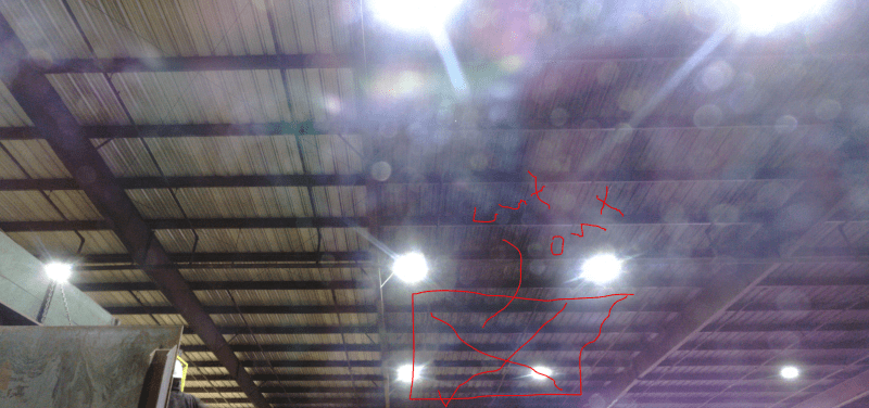
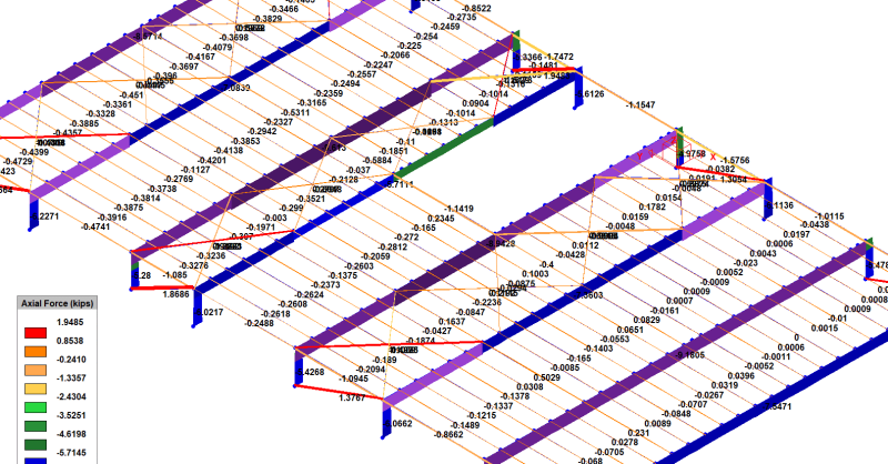
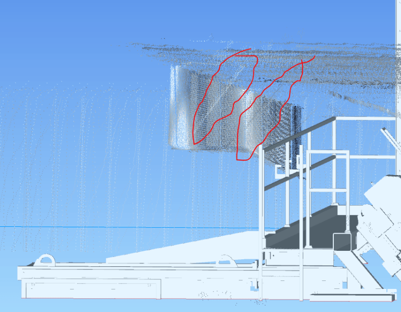
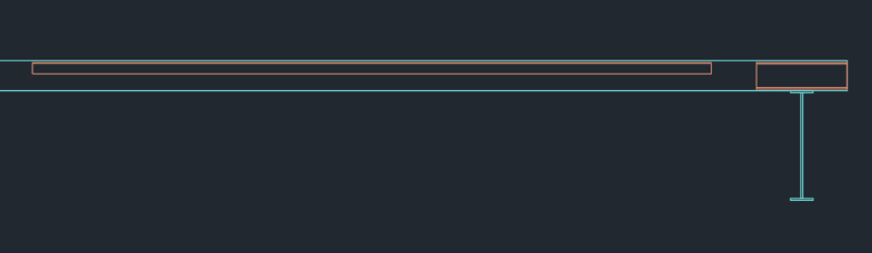
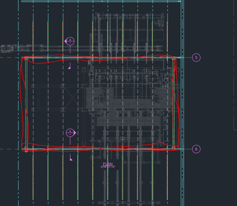
I wanted to get some opinions on the modifications I am planning on doing for an existing PEMB roof. This is related to another post I had on a PEMB roof addition (same project). I designed a new supporting structure and foundations for an additional enclosure sticking through the roof of an existing PEMB:

Capture2_hijyy9.png
Capture_rzmva4.png


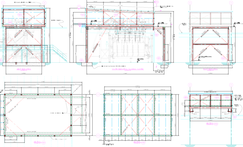
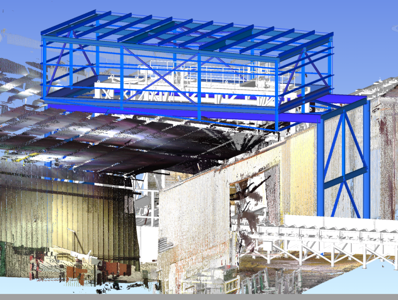
I am now in the process of designing some reinforcing for the existing building.
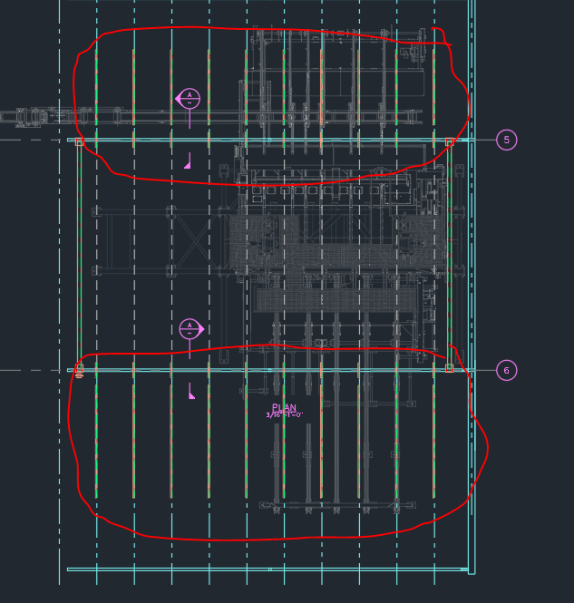
There is very little information available to me on this building so I have made a lot of assumptions when deciding how to reinforce around this opening in the PEMB.
There are two main items I am adding but I am getting pushback on one of these items and wanted to get some outside opinions:

Item 1)
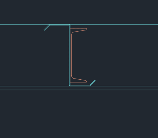
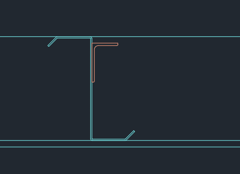
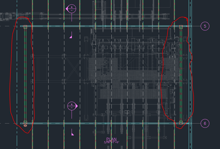
I plan to reinforce all the existing purlins around the structure for additional snow drift. Even though the ground snow load for this area is only 5psf, I believe the snow drift will be significant enough around this structure ~60psf max. I plan to use bolted or welded C channel or angle or both

Capture3_egd4pq.png
Capture4_d5t6a1.png
Capture5_ioeeue.png
Capture6_gn9cgj.png


Item 2) (the one I am getting pushback on)
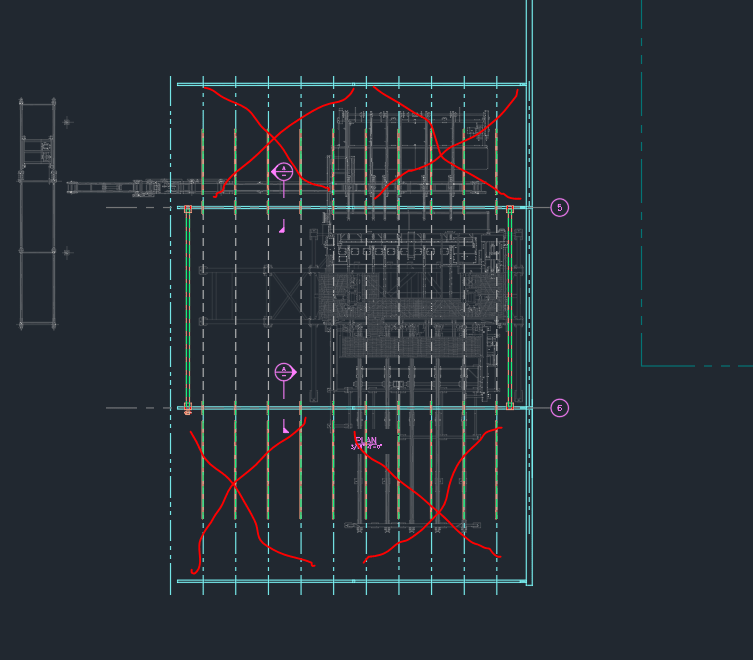
I assume that even though the eave struts in PEMB transfer most of the lateral load to the LRFS, there will still be some possible axial loads in those purlins that are being taken out that needs to be accounted for. I figure that since the extra load would be transferred to the purlins on each side of the opening, I need to add some reinforcing members between the frames there to account for this excess load that would otherwise fall on the existing eave strut and other purlins

Capture7_o1rw3o.png
Capture8_jfrwx6.png


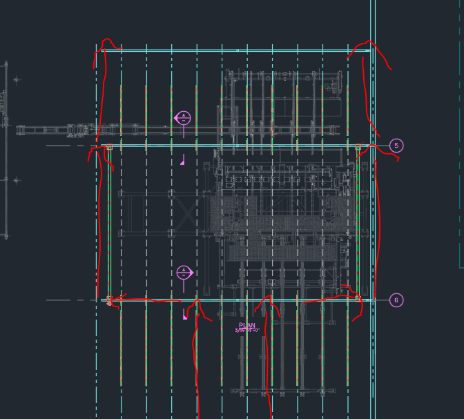
In order to transfer this load I would also have to make that main frame much stiffer in weak axis bending so it could actually attract this load and transfer it to the outer reinforcement because I believe as it is the frame is probably so weak in out of plane bending that it would not be attracting that load. So in essence I am making a stiff box around this opening that will hopefully attract any load that the removed purlins would have been taking

Capture9_qxo9sf.png


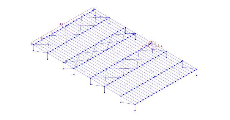
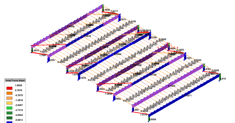
I have been told that this second item seems unnecessary, but I am planning on doing a rough model to see if I am justified in this. Can I get some opinions on whether this seems necessary to do? I must note that there are no building drawings for this building, and there are no complete models. There is also no intent by anyone involved in this project to have a full model of the building created to check these modifications.
 
Replies continue below

Recommended for you

The repairs to the pre-eng for the new drift loads will be extensive. I would expect extensive modifications to the existing frames. New roof girts and on and on. You will need to plan to spend a lot of time on site measuring the existing frames.
 
canwesteng, from the pics I have there appears to be rod bracing in the roof at the adjacent bays. But oddly doesn't seem to be wall bracing in these bays

Capture11_z6ciax.png

Capture10_peybiy.png
 
I recommend walking through the lateral load path from the end walls to the vertical bracing. Start at the end wall girts, which flow wind load into vertical wind columns. The reaction at the top of the wind columns will push against the roof plane. The purlins in the roof plane will be loaded axially and bear against the horizontal roof truss bay. The horizontal roof truss will have tension members (rods/cables) and compression members (purlins). The horizontal truss will span across the building and have will have end reactions at the longitudinal walls. The eave struts act as a collector to distribute that horizontal truss reaction to the vertical braced bay.

I think once you study that load path, you will find that removing the purlins in that bay between the horizontal roof trusses will not interrupt the load path. The load essentially flows around that roof bay when the horizontal trusses take their reactions out to the eave strut collectors. Therefore I do not believe the existing purlins will see any additional axial load.

I have used cold-formed Cees to screwed to the purlins to reinforce for drift. But you will have to check the existing main frames as well if they are seeing a net snow load increase. Hopefully that's not the case since their tributary width is being cut in half.
 
Agreed with bones - I think validating what is the vertical element of lateral force resistance should be done though. If there is no wall bracing, check for portal frames there.
 
Note that Pre-Eng building will use multiple bays of roof bracing often depending on the building length. If the building is 200' long, there might be 3' bays with roof bracing, each taking 1/3 of the lateral load down to the eaves as bones described. The remainder of the load is taken through the roof purlins and distributed down the building to the next braced bay. If you remove the purlins, you will have extra load that needs resolved through the frame bending. I would consider adding roof bracing on either side of the opening as needed to help limit the load.

Lastly, remember to take into account losing continuity of the purlins, in addition to the drift loads.

Go Bucks!
 
Another consideration is apply the windward and leeward wind loads separately, rather than lumped together on the windward wall. That provide be a more accurate representation of the wind load distribution in a roof with a big hole in it.
 
Thanks for the explanation of that load path bones. I haven't worked very often with PEMB's so it is very helpful to see how the load is travelling through them. I see how the horizontal trusses would help transfer most of the load out to the eaves, but there must still be load travelling through the purlins that must be accounted for especially right close to the eaves. I ran a really rough model to see how this would work and I got more load in those outer members once the purlins were removed

2024-03-12_09h02_10_qztfbn.png
2024-03-12_09h02_52_ugdxld.png
2024-03-12_09h05_43_ozwv1j.png


Now I now this load is technically not applied correctly, and I also have a limited software license that is nota able to model tension only bracing or run non-linear analysis, but I thought this would in general still be the same situation regardless of how accurately it was modelled: excess axial load and bending to account for all around that opening
 
I would also be doing a much more thorough model and field verifications and measurements if I could, but I work for a construction company that does not see the same value or need for engineering as I would hope. I just try to do the best job I can with the information I have available, which for this job is not a lot.
 
So it has 4 bays of vertical bracing but only 3 bays of horizontal bracing?

straub46 made a good point about the 1/3 lateral load sharing assumption being impacted by the purlin removal. But I do think that if you apply the windward and leeward components separately, that should alleviate the opening effect to some degree.
 
There is clearly a 3D laser scan. I have extracted information from those before. Were you provided that information?

Assume zero new load to existing PEMB and reinforce assuming the utilization is at 100%. I think a feasibility study should have been completed first.

Your pre-eng will have many flange braces. At those flange braces you will likely find the gauge of the purlins changes. Taking out flange braces is a big deal. Some flange braces will be one side, others will be two sided. Any two sided flange braces must be looked at carefully.

Depending on the drift load added I would expect you will need new purlins, so reinforcing may not be the main issue. Your existing cladding will not be designed for any drift load, so that is a problem. I would start by looking at the changes in gravity loads. I doubt the bracing is a huge challenge to overcome. Gravity loads will be a big deal considering the amount of welding needed if you have skimpy materials like you see most of the time.

 
ya the number of bays and bracing are not accurate because I only have some pictures and a semi decent scan of some interior to go off. It is a 500'X260' building so probably like 16 bays. I was just modelling a few bays with some random bracing to see what the load path would look like in general. I am not able to go to site and have no drawings of the original building. Like I said the company I work for has the old school mentality of just getting stuff done without any need for legitimate engineering, so I am trying to reinforce a building I really have no info about, so I am just trying to make worst case scenarios and be extra conservative.
 
As an engineer, none of that changes your job or the rules. This is an occupied building.

Below is a typical pre-eng frame you can be provided by suppliers. This is new, so one can expect every step is scrutinized to save pounds of steel. If you have an old building, the amount of automation was much less, so there can be some fat in the design. Below that you can see the frame member sizes. It is ridiculous. These work if built as designed, but I have seen endless ding dongs take out things they should not. We had one client that wanted to take out some flange braces for a crane. They lost their marbles with the new beams required to allow them to remove a flange brace from each bay line.

PRE_ENG-1_ffho50.png


PRE_ENG-2_xsqtne.png
 
Brad805, I completely agree. I have had countless confrontations with my boss about what NEEDS to be done for all our engineering design. At the end of the day I am only allowed to do as much as my boss lets me, otherwise he has no use for me as I've been told. To put things in a little more context, I am an EIT and I was the only "engineer" working here for quite some time. Which is why forums like this are invaluable to me. They recently hired one PEng to be able to stamp a very small portion of things that they absolutely cannot get away without stamping. Everyone else is a drafter/designer without an engineering background. My boss is not an engineer. I have told my boss that once I have my PEng I will not be working for him if things aren't done properly, but unfortunately for now I don't have any say in these matters and all I can do is continue to advocate for proper engineering as much as I can without crossing the line where I'm out of a job.

As for the scan data. I do have access to it, but it does not give me enough information to be able to model this whole building or see all the details. I have a decent scan in the area that this roof is being opened and it does look like there are a set of one sided flange braces that will need to come out. all of the purlins are being reinforced and I was thinking I could just move these braces to the other side of the frame and attach them to the reinforced purlins.

Capture_p8tw58.png
 
You can get the basic frame geometry from the scans quite well. We use Revit for this quite frequently. It works very well with point clouds. You need to get your view plane set to the frame lines very well, and then play with your depth settings. With some practice and thought how the scanner is working, you will be able to decipher what many points are. Your view depth is very large in the image posted, so you cannot figure out much with that. If you do not have any software, it will be tough. CAD does not work great because it lacks view depth control. If you have the full version of CAD, you can extract sections along any line. The scanner will have collected millions of points. The problem is things are in its view path. It still collects data, but you end up missing what is important to you. You have to dig thru the data.

If you able to post a link to the point cloud I would take a look on my own time. You are clearly trying to do what you should.
 
Thanks Brad805, that is really kind of you, but I will go through the scans some more and see if I can't come up with a half decent model to estimate some loads myself. It's just super time consuming because I am working off a laptop. I don't actually know who this scan belongs to so I don't feel comfortable sharing it.

But for now I am going to go ahead and assume that I will be needing extra reinforcing all around that opening until I can show otherwise.
 
Status
Not open for further replies.
Back
Top