Continue to Site

Eng-Tips is the largest engineering community on the Internet

Intelligent Work Forums for Engineering Professionals

  • Congratulations KootK on being selected by the Eng-Tips community for having the most helpful posts in the forums last week. Way to Go!

Modifying base and top on solid geometry for hexmesh

Status
Not open for further replies.

tstanley

Mechanical
Jun 1, 2001
149
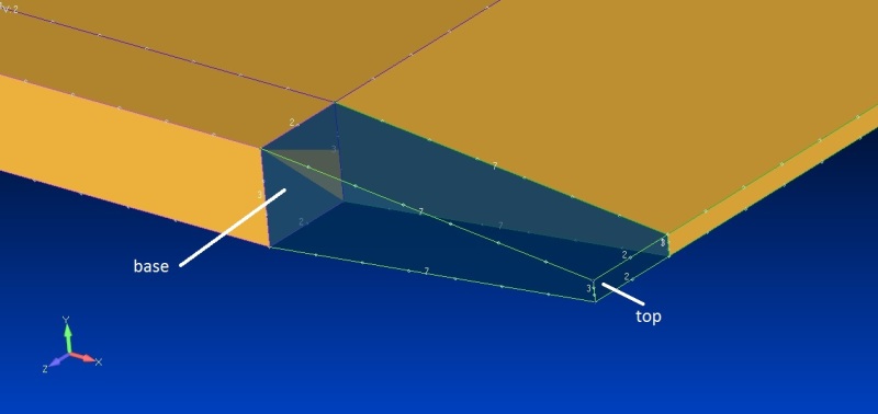
I have some solid geometry consisting of a number of tapered brick shapes, six sided. The existing top and base are different sizes so I do not want them to have the same number of nodes per side. However the other two pairs of sides can have the same number of nodes per side and would work for hexmeshing the way I would like. I could just redraw them but there are quite a few so it would be easier just to use a command to select the sides that would be better for the top and base. In help there doesn't seem to be a command to do this. Doesn't seem to be any command under modify or geometry.

When the mesh sizes are set manually on the solid, then the hexmesh fails because the top and base do not match.

Any ideas?

Tom
 
Replies continue below

Recommended for you

I am still trying to find an easy way to modify the base and top to a different pair of surfaces. I came across a reply to a different post by Blas Molero that suggested using mesh control, approach on surface, and removing any links or matching between the surfaces that are giving me problems. It did not work for me:
base_and_top_yhrwkt.jpg


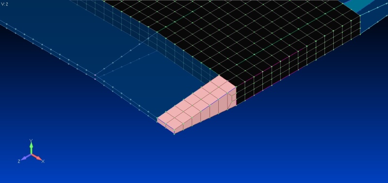
In this model there are 192 solids like this and somehow one of them meshed using the hexmesh solid command and came out with a reasonable mesh:
base_and_top2_wuxrip.jpg

When you slice a solid for hex meshing, what determines which surfaces become the top and base?
Now that the model is already sliced I hate to start over again. Should I submit a request for a new command?

Tom
 
I have resolved the issue. It seems that the order of steps is important. After preparing the geometry and then setting the size on the surface, then go back and ensure all the size along curves are what is desired. Then use the command Mesh Control, Approach on Surface to remove all the slaving by selecting "not specified". Finally go to Geometry, hex mesh solids. Somehow it seemed that if the size along curves was done after slaving was removed, the slaving was reset.
 
Status
Not open for further replies.

Part and Inventory Search

Sponsor