Eng-Tips is the largest engineering community on the Internet

Intelligent Work Forums for Engineering Professionals

  • Congratulations waross on being selected by the Tek-Tips community for having the most helpful posts in the forums last week. Way to Go!

Mold Locked Design..Multiple Side Action/Collapsible Core? 2

Status
Not open for further replies.

CPosner

Mechanical
Jan 26, 2007
139
0
0
US
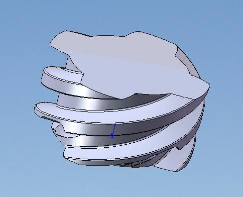
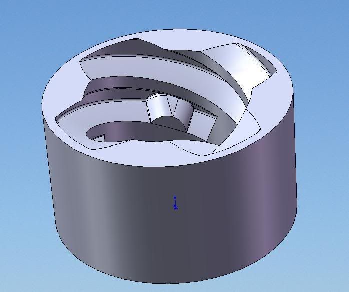
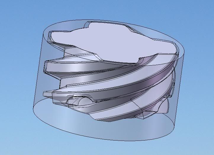
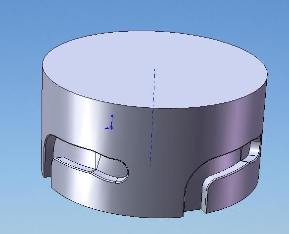
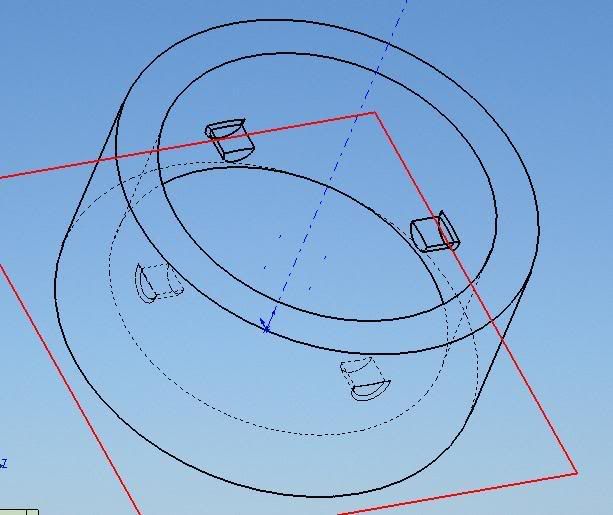
I've got a design that is currently Mold locked. It consists of two mating parts. The issue is with the Female part. I know by opening the bottom, it can be made and by eliminating that undercut.

I'm looking for some suggestions on how to make this design work. The design can change, but the intent is a "twist-fit" connection that must be removable, multiple times. Must be a Robust connection.

cam.jpg

followers.jpg


Thanks in advance.
Chad
 
Replies continue below

Recommended for you

You could make it as is. You'll need lifters on the female part and 4 slides on the male.

As you said, you could eliminate the need for lifters on the female part by opening up the bottom.

You could also eliminate the need for slides on the male part by blowing out the undersides of the cam paths.

-b
 
I see no real problems

You need the parting line of the core on the female part to be level with the flat side of the engagement dogs. This means a core on both halves.

You absolutely need side cores or an unscrewing mechanism. Side cores will be a lot easier.

Regards

eng-tips, by professional engineers for professional engineers
Please see FAQ731-376 for tips on how to make the best use of Eng-Tips Fora.
 
This is good news to me! Thanks for the quick responses so far.

I can visualize how the male part will be made.

bvanhiel, I could blow out the underside of the cams, but I would lose the aesthetic. I wish I could do that...Unless there is another approach to have same Diameters on both sides.

but...I am having trouble visualizing the female part still.. I am not familiar "lifters"

patprimmer or bvanhiel, could you try to explain the mold actions for the female part.

Thanks
 
Any half competent moulder or toolmaker should be able to show you examples.

It simply opens in line of draw.

It will need some draft from both ends toward the parting line of the core.

The cores will need draw polishing.

You will need an undercut on the moving half core to ensure it stays on the moving half during mould opening.

You will need a stripper plate to get it of the moving half core after the mould is opened.

I would think a sprue running down the centre of the core with say 4 sub gates into the inside bore of the female part half way between each locking peg or dog.

The drawing shows no radii at any corners. They will be necessary to avoid breakage t the stress risers.

The slots will need 4 side cores, or some side edges of the slot will need to be laid back to line of draw of the side cores if you want to get away with only 2 side cores.

Regards

eng-tips, by professional engineers for professional engineers
Please see FAQ731-376 for tips on how to make the best use of Eng-Tips Fora.
 
You do not say which material, so I am not considering special requirements foe specific materials.

Any reputable raw materials manufacturer will have technical bulletins that show how this works, and any basic mould design book will show it.

Regards

eng-tips, by professional engineers for professional engineers
Please see FAQ731-376 for tips on how to make the best use of Eng-Tips Fora.
 
I don't understand why you made the pins half-round. That gives up half the strength, and the edges can cut into the mating part during some parts of the mate cycle.

Speaking of strength, a coarse, possibly multiple lead, Acme or buttress thread would be _much_ stronger, and could still have a locking feature when fully engaged, e.g. with a bump on the male thread and a dull hook in the female thread.

What you've got is a topologically inverted adaptation of a BNC connector; but those are _always_ made of metal; the design is not robust in plastic. Consider instead adapting the design of MS twist-lock round shell multipin connectors, traditionally made in zinc, but the geometry would be robust in plastic too.


Mike Halloran
Pembroke Pines, FL, USA
 
Fillets would be added to the original design, those little dogs would be fully filleted, they were quickly truncated at the top for clearance, but there is more room to round the tops rather than flat.

Thanks, for the tips, still a little confused about how the female part is made...I guess I need to actually see some tooling that does the same/similar thing.

Anyways, as per Mike's suggestion, Here is a rough design with a 4 lead acme twist-lock. Wasn't sure about your dull hook and male bump..I visualized it in reverse bump on the female and notch in the female at the bottom of the threads... see below:

MaleAcme.jpg


femaleacme.jpg


femaleacme.jpg


Thanks,
Chad
 
Seems like my first design is simpler. I can increase size to reduce stresses..But my concern is durability of the plastic after X amount of cycles. I am looking to get a RP model made this week..test it for functionality. I'm thinking about FDM..any other suggestions?

Also, does anyone think I should reverse the male and female, put the Cams on the inside, that way the dogs are on the male part. Due to mounting conditions, the female part is not removable, that way if a dog does break, the male part can be replaced.
 
If the cam is on the inside you will need a complex unscrewing core.

Leave it how it is for reasons of tooling costs.

Improve the strength of the dogs.

Use a material that will take the load. GF nylon maybe, depending on the load and other environmental factors.

If you need a glass filled material, warpage or distortion will be an issue due to differential shrinkage along and across the flow.

Regards

eng-tips, by professional engineers for professional engineers
Please see FAQ731-376 for tips on how to make the best use of Eng-Tips Fora.
 
Yeah, that's the general idea. The bumps probably don't need to be that obvious. If they're a little more subtle, you may be able to just unscrew the core out of the female part, or rather unscrew the core to eject the part. Of course you need to stop the the threads instead of tapering them to a knife edge.


Mike Halloran
Pembroke Pines, FL, USA
 
heh..two conflicting posts about unscrewing dies...

In terms of material..I think something with higher abrasion resistance and also higher corrosion resistance due to sea water exposure.


What precision do you require, what is the environment, how variable is the environment.

Many screw together parts that are used in boat fittings are made of nylon.

Swelling can be an issue, but not to the degree that some suppliers of other materials might infer.

All materials have their strengths and weaknesses and we need to know all the details to work out the best overall compromise.

Regards

eng-tips, by professional engineers for professional engineers
Please see FAQ731-376 for tips on how to make the best use of Eng-Tips Fora.
 
I would require close fit for this application. The restraint feature is pretty key to how the unit functions. Operating temp is like 25degF to 95degF and will be fully submerged in sea water ..nothing too extreme
 
Depending on load, fatigue , Acetal might do, or PET or PP

Regards

eng-tips, by professional engineers for professional engineers
Please see FAQ731-376 for tips on how to make the best use of Eng-Tips Fora.
 
UPDATE:

I got a polyjet Rapid Prototype of the parts. I went with a variation of the first design and it turns out the peg diameters are too large, hence making the snap way too difficult. Also, dimensional tolerances of the RP weren't what I expected, so a little sanding was required. btw, what dimensional tolerances can I expect from an Injection Mold?

I think one solution is decreasing the pegs' diameters or further investigating the screw option. I think what I initially drew was too large of the thread.

Any recommendations on the thread size/dimensions? OD of the male thread is appx 1" - 1.25"

Thanks!
 
Status
Not open for further replies.
Back
Top