Continue to Site

Eng-Tips is the largest engineering community on the Internet

Intelligent Work Forums for Engineering Professionals

  • Congratulations KootK on being selected by the Eng-Tips community for having the most helpful posts in the forums last week. Way to Go!

Moment capacity of steel fin plates

Status
Not open for further replies.

intrados

Structural
May 24, 2016
6
Would anyone be able to shed any light on how to best determine member moment capacity for plates being bent such that the narrow edges of plate are the extreme fibres? i.e imagine where a beam consists of the web only of a universal beam/col when bent about major axis without any flanges present. Buckling of compression edge will obviously govern but I cannot deduce how to quantify moment capacity from standards. Particularly with respect to AS4100. An example of the scenario I’m designing for is shown in sketch attached where a deep plate is cantilevering from eave/knee of portal frame. The plate in question is to have timber laminated to each side of plate which will further cantilever. Said timber will no doubt provide ‘some’ buckling resistance but will be considered negligible in this case. An addition of a top flange to make a ‘T’ is not an option.

Thanks in advance for your help.
 
 http://files.engineering.com/getfile.aspx?folder=12b72ccc-77fe-47c5-abe1-54a83320f897&file=DSCN1959.JPG
Replies continue below

Recommended for you

Determining the section capacity of the fin plate (local buckling) should be straight forward by following Cl. 5.2 of AS4100.

As a starting point for member buckling I'd follow Cl. 5.6.2 for a segment unrestrained at one end and use the equations for a constant open section to determine the reference buckling moment. I would assume Iw = 0.

There's a little more info in appendix H.
 
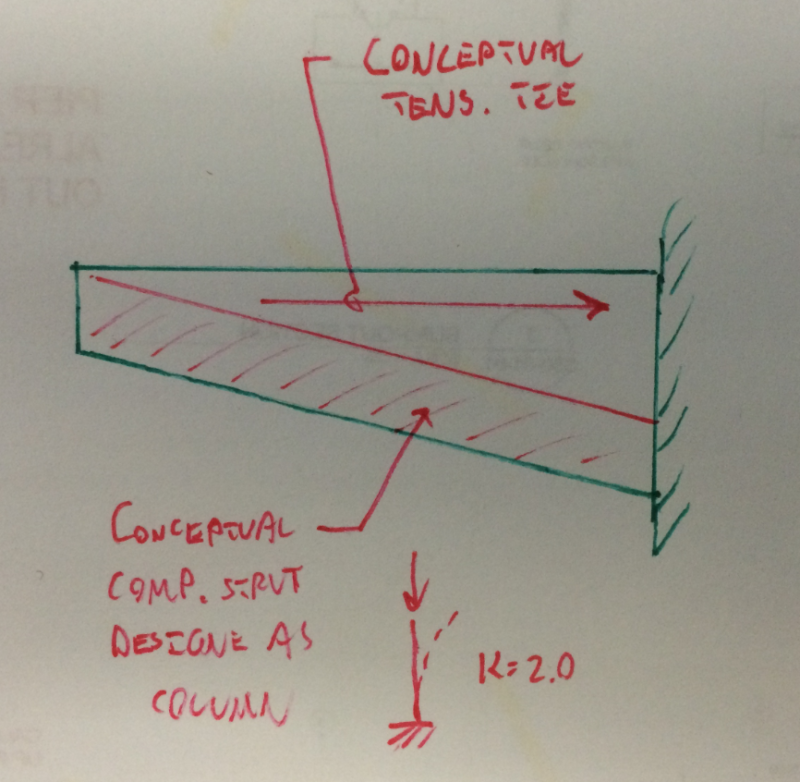
My knowledge of Aussie codes is sparse so I can't help you much there. However, I've had some success with the design model shown below. Basically, I treat the plate as a truss with tension and compression chords. The method is quick to apply, reasonably conservative in my opinion, and can deal with the non-prismatic nature of your section. You're capacity will be small but, then, I imagine that your demand is too.

Capture10_dqckog.png


I like to debate structural engineering theory -- a lot. If I challenge you on something, know that I'm doing so because I respect your opinion enough to either change it or adopt it.
 
Another option - I have used the double coped beam provision in AISC 13th Ed. page 9-6 for a similar situation. AISC says that you can use it for extended single plate connections. The only thing to do is to evaluate at intervals with an appropriately conservative plate depth (a bit deeper for buckling, a bit shallower for yielding).

"It is imperative Cunth doesn't get his hands on those codes."
 
Thanks for responses.

handoflion - Reference buckling moment seems to be fairly straight forward. Iw = 0 agreed. It's actually the effective section modulus that stumps me. I assume i'm dealing with a 'slender section' but Ze still requires input of slenderness limits that don't seem applicable without having one or both longitudinal edges supported (table 5.2). Similar problems occur with calculation of 'b' in section slenderness - clause 5.2.2.

I could perhaps use a conservative value for Ze and not worry about including slenderness limits but what would this be? Simply bd2/6? I can't be comfortable that slenderness limits should not amount to a coefficient of <1.

Thanks for other posts too guys.
 
If you google Design of Unstiffened Extended Single-Plate Shear Connections there is a pdf on Larry Muir's website explaining how to design shear tabs, one of the checks is plate buckling. If you want to apply macgruber's method but don't have the AISC manual I'd go with that.
 
MacGruber said:
Another option - I have used the double coped beam provision in AISC 13th Ed. page 9-6 for a similar situation. AISC says that you can use it for extended single plate connections. The only thing to do is to evaluate at intervals with an appropriately conservative plate depth (a bit deeper for buckling, a bit shallower for yielding).

canwesteng said:
If you google Design of Unstiffened Extended Single-Plate Shear Connections there is a pdf on Larry Muir's website explaining how to design shear tabs, one of the checks is plate buckling. If you want to apply macgruber's method but don't have the AISC manual I'd go with that.

I'm not so sure about this. The extended single plate provisions check local plate buckling assuming that there is rotational restraint at both ends of the plate. If the cantilevered end of OP's plate is not braced rotationally somehow, this method will not capture a global lateral torsional buckling style failure which I would expect to govern.

I like to debate structural engineering theory -- a lot. If I challenge you on something, know that I'm doing so because I respect your opinion enough to either change it or adopt it.
 
The critical buckling stress equation for double coped members in AISC's Steel Construction Manual is similar to eq F11-4 for bars in the AISC specification. Except C[sub]b[/sub] replaces f[sub]d[/sub] (where f[sub]d[/sub] = 3.5-7.5d[sub]ct[/sub]/d and d[sub]ct[/sub] is the depth of the cope).

But, I don't know if the "fin" can be considered to be a bar. If it is 8" or less, it should meet ASTM A6's definition of a bar. AISC's Steel Construction Manual doesn't have a definitive answer. In the plate products section of chapter 1 it says ". . . flat stock has historically been classified as a bar if it is less than or equal to 8 in. wide . . ." and "There is very little, if any, structural difference between plates and bars."
 
KootK said:
this method will not capture a global lateral torsional buckling style failure which I would expect to govern.

AISC 13th said:
page 9-8, When a beam is coped at both flanges, the available buckling stress is based upon a lateral-torsional buckling model...


"It is imperative Cunth doesn't get his hands on those codes."
 
I believe that Koot's concern with the shear tab analogy is still valid regardless of that quote from AISC. Their model still assumes each end of your plate is rotationally restrained no? In the case of a fin plate I don't see the outer edge as restrained. Perhaps you just use a length equal to double in your calculations but I fear that may be overly conservative.
 
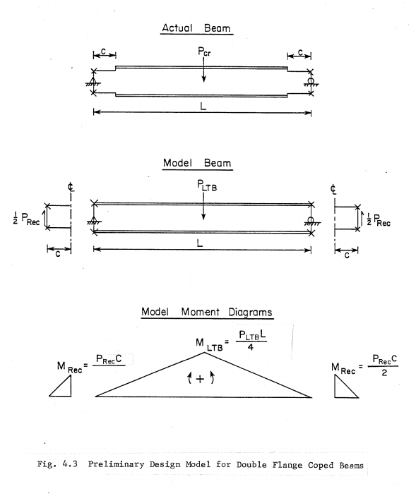
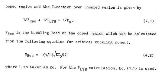
I may have to cut and run on you Jayrod (good call about the double length though). The clips below are from the 1984 source doc by Cheng and Yura. The ends of the coped sections are indeed restrained against rotation. However, they use twice the cope length in the buckling equation. In the end, we may be comparing two equivalent conditions here:

1) LTB simple span (2.0 x C) with the ends prevented from rotating.
2) LTB cantilever span (1.0 x C) with one end free and the other fixed against rotation and warping.

Regardless, I get the impression that the design method for a prismatic plate just comes down to the classic elastic LTB equation. How to handle the taper properly is an interesting wrinkle though. Base it on the deepest, shortest, or average section? That's one of the things that I like about the method that I pitched above. It actually deals with the taper explicitly.

The analogous tapered beam for LTB evaluation would be shallow at the ends, where faux rotational restraint is present, and deep in the middle where the restraint is essentially warping restraint due to symmetry.

Capture11_v6kdkr.png

Capture12_zhcw33.png


I like to debate structural engineering theory -- a lot. If I challenge you on something, know that I'm doing so because I respect your opinion enough to either change it or adopt it.
 
No worries, bail on me. My general opinion was you'd treat it similar to every other cantilever analysis and just double the simple span stuff. It appears as though I'm at least partially correct, must be luck.
 
I've done this by drawing out a triangular stress distribution to get the extreme compression fibre stress. Then I calculate buckling stress of a similar thickness column. Pretty similar to KootK's method.

I have, however, seen equations somewhere with lateral torsional buckling checks for a vertically aligned plates. If it isn't in the AISC spec, it was likely in Ziemian's "Guide to Stability Design Criteria for Metal Structures". If I remember, I'll take a look.
 
I think I'll run with the truss analogy for now. I'm not too concerned with over designing (from a potentially slightly conservative analysis) considering the relatively insignificant increase in cost that may occur. I'd rather be comfortable knowing that it has actually been designed. It will only add to my knowledge to make more empirically (yet safe...) based design judgements in the future :)

Thanks again for all replies

 
Status
Not open for further replies.

Part and Inventory Search

Sponsor