Eng-Tips is the largest engineering community on the Internet

Intelligent Work Forums for Engineering Professionals

Moment Connection for Beam on top of Extended Beam Seat 5

Status
Not open for further replies.
Replies continue below

Recommended for you

If you just weld the overlapping beams, the top flange would be unrestraint and might result in distortion in beam web with bending. Maybe you could run an endplate and back it up to the supporting beam??
 
In order to get any significant moment capacity, you would need a tension strut from the top flange of the I-beam to the seat the restrain the top flange. The tension strut would have to be larger than the top flange (by 1/COS of the angle) and be rigidly connected to the top flange of the seat beam. Otherwise, to get moment capacity you would have to bring it down to the same level and use splices.

As far as the welds, the necessity for full-pen welds vs. fillet welds usually depends on the fatigue stress capacity required.
 
A moment connection would be possible in this configuration, but it would be difficult to achieve and costly. You'd need diagonal and vertical stiffeners in both beams to transfer the flange forces from the upper beam to the lower beam.

Why would you have this configuration and require a moment connection?
 
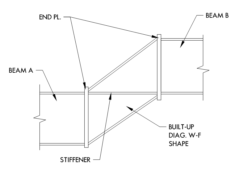
I see eight vertical beam stiffeners in your future. If you actually need diagonals or web doublers, I'd take that a sign that you're headed down the wrong path with this.

It would be good to know what percentage of the full member moment capacity you're hoping to develop here. This arrangement can work for small moments but I'd suspect that large ones would be a problem.

With the right stiffeners etc, I think that you could get the job done with fillet welding etc. As you've shown it, however, I see a lot of flexibility in that connection. Basically the flex induced in both flanges. That'll tend to neuter what you're trying to accomplish.

I like to debate structural engineering theory -- a lot. If I challenge you on something, know that I'm doing so because I respect your opinion enough to either change it or adopt it.
 
As discussed, the moment capacity of any connection will depend on the magnitude of the loads being applied. For any significant loading, the connection you show will allow rotation (Top Flange not restrained, prying action of flanges at welded connection, etc.). See attached sketch for conceptual ways to improve the moment capacity of this type of connection. Also, I just have to ask if you could just do a conventional beam splice vs scabbing onto the top.
 
 https://files.engineering.com/getfile.aspx?folder=07cb2017-ea09-41da-83ae-1299f2f2acdd&file=scan0084.pdf
This is basically a simple beam, but because of clearance issues below in the mid-span and above at the end of the spans, the end locations of the beam need to be lower than the main span of the beam.
Moment at mid-span is about 200 in-kip, but with pinned end connections the moment at the connection in question is only about 10 in-kip. (Total span is about 13.5 ft.)

Thanks for all of the responses. Very helpful

All I know is P/A and Mc/I
 
Note that an ALL-AROUND fillet weld as you've shown it is not a good idea - you never want to drop a fillet weld over-and-under a change in plane surfaces as you've shown it.


Check out Eng-Tips Forum's Policies here:
faq731-376
 
How's this for a concept? Cut the middle beam short and provide a "kinked" connection:

kinked_w-f_khal4b.png
 
Status
Not open for further replies.
Back
Top