Continue to Site

Eng-Tips is the largest engineering community on the Internet

Intelligent Work Forums for Engineering Professionals

  • Congratulations KootK on being selected by the Eng-Tips community for having the most helpful posts in the forums last week. Way to Go!

Moment Connection(?) for Timber Truss 1

Status
Not open for further replies.

skade

Structural
Oct 2, 2017
4
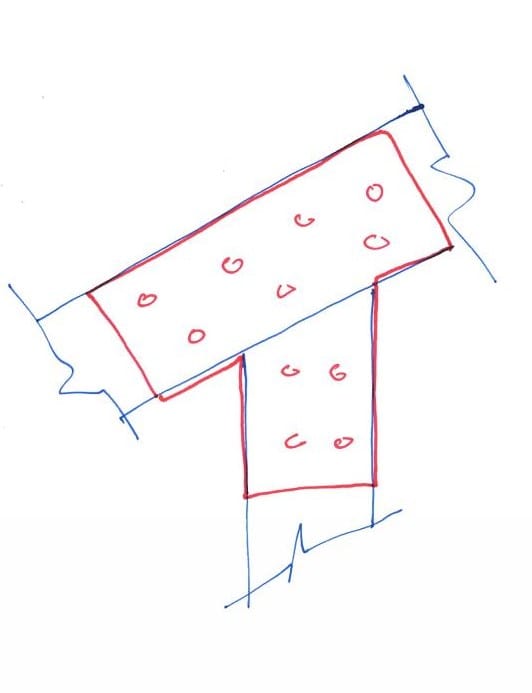
I am attempting to design a moment connection for the top-chord-to-post connection for a timber truss (diagram attached). I realize that this is a connection best avoided; however, I am trying to accommodate the architect's vision. The design is inherently unstable if all connections are pinned, so I modeled it with fixed connections at the locations mentioned above. I've done a few other timber truss designs, but none as nasty as this one. I'm thinking of trying to use steel dowels epoxied into the members, but I'm having trouble finding design values (though I doubt I'll be able to develop the loads needed).

The connections I've considered so far-- straps, bolts, plates, etc.-- I don't believe will give me the needed fixity. I also realize that there will be further design considerations if the epoxied dowels are a viable option, such as moisture content, shrinkage, etc. Also, other geometry options would ruin the desired aesthetic... it would be so easy if I could push the bottom chord up a couple of feet...

Any ideas? Tips very much appreciated :)

(Experience: EIT, 1.5 yrs)
 
 https://files.engineering.com/getfile.aspx?folder=c8ba34a3-d5ea-48fe-8677-342833321789&file=truss_connection.pdf
Replies continue below

Recommended for you

Maybe something like the attached sketch would work for you. Steel side plates each side (continuous plate across the joint), either thru-bolt or lag screw. You can extend the plates as long as you need to transfer the force from wood to steel, then the steel plates do all of the heavy lifting at the joint.

timber_connection_lvqqbl.jpg
 
That's actually what I had originally designed, and then I was told that I couldn't consider plates and bolts in that configuration to be a fixed connection... I understand when you only have two bolts that a slight difference between bolt diameter and hole will produce movement, so I guess the same applies to a larger bolt group, to a lesser degree?

It was recommended that I try the dowels and epoxy or a bucket connection. Or maybe I'm over-complicating it?

Thanks for your response CANPRO!
 
Why not consider a mortise and tenon joint with pegs. I don't have a good reference for this design, but there seems to be some research posted on the internet.

At first blush, I don't see much potential in the epoxy rod idea. Where would you find capacity in end grain withdrawal?

(also I'd remind your architect that in traditional timber construction, there are diagonal braces)
 
I suspect you'd need more than 2 bolts per member - strength considerations aside, you can provide as many as you feel necessary to get a rigid connection. Any bolted connection will have some play in, how much movement can you tolerate? If you use lag screws, that will eliminate any play in the fastener to timber interface, and the holes in the steel should have to be 1/16" oversize for the lag screws.
 
At first glance, it looks stable to me without moment connections but maybe I am missing something. In any case, if you absolutely need a moment connection, my first choice would be the plate idea as suggested above. The steel plates will be significantly stiffer than the wood members they are attached to. My next choice would be a sleeve or tube around each member in the connection (similar to the [plate configuration, only with tubes).
 
Without getting to far into it, has some really great 'invisible' connectors I have used in the past - I get the feeling your architect is shooting for a naked wood look.
 
kipfoot: Cool idea with the mortise and tenon-- not sure I'll be able to dig into that for this project. Yeah, the epoxy was one not-so-great idea.

CANPRO: Good point-- will keep in mind for future projects.

MotorCity: Turns out you're right. With the roof diaphragm and the rest of the configuration I have pictured, I actually don't need to consider the truss action... so I went down the rabbit hole for nothing on this project. I'll have to chalk this up as a learning experience.

Signious: Thanks for the resource-- I'll check those out.

...

Turns out my original assumptions about the need to treat the configuration as a complete truss system were incorrect, so I am looking at it instead as top chords acting as cantilevered beams to take the point load from the ridge beam and bearing onto the cross beam below, with Simpson concealed beam ties and concealed joist ties. Thank you everyone for the input! I've got a lot to learn...
 
kipfoot: You can do great things in withdrawal in endgrain, if you do it right. Rotted off ends of timbers embedded in masonry walls can be cut off and repairs spliced in to the timbers with rebar dowels just like concrete. It's actually common if that's your line of work, and 40 year old research backs up the field practice.
 
Looking at your sketch and it doesn't look like a truss, unless you are trying to get Vierendeel truss action.

Why are you trying to get moment capacity at the joints?
 
kipfoot: Google "epoxy timber repairs UK" to get a lot of good info. Rotafix in particular is really good because they've been doing it for a long time on very sensitive structures, but the National Research Council (Canadian) carried out some good practical research a few decades ago. I started using their methods in the '80s and it's applicable to more than restoration. I'd send you a scan of a good document (that I used as a starting point) if you are interested. I'm not sure of protocols and I don't really want to post my email here, let me know if & how you want to do that.
 
OldBldgGuy: thanks for the offer, but I don't have a need for it. It's interesting to know it's out there, and I found a few references in the U.S. that I could contact when or if I ever need to.
 
It's been several years since timber design class, but I remember the prof recommending embedding a steel ring set into a large diameter (about 1/3 of the beam width) hole with a depth up to 1/4 of the thickness, to provide a strong, stiff connection to timbers. It can extend out through a matching sized hole in the steel plate or be fitted with a washer and a bolt. Two of those on each leg would provide a very stiff connection for moment.
 
skade,

For future reference, the timber framing books by Steve Chappel have some good engineering information for traditional mortise and tenon style timber connections.
 
Thanks bones206-- I'll have to check those out. I've just been working out of NDS so far, but for my own interest I'd love to learn more about more traditional methods of timber connection.

OldBldgGuy, thanks for the tip. I haven't gotten too deep into repairs yet, but I certainly could at my firm, and I'm interested in building restoration. Makes sense they'd be doing a lot of that in Europe.
 
One other thing to keep in mind - when you introduce large steel plates bolted like some of the sketches above, the connections will likely develop cross-grain tension and split (due to the extreme rigidity of the steel compared to wood coupled with the wood shrinking), rendering the connection useless. The NDS sets rules for max spacing between bolts in adjacent rows on the same steel plate and I believe AITC has a document discussing use of connection plates like what was sketched above (link is here:
 
Structural dood,

Would you mind further explaining how the connection would develop cross grain tension if the wood shrinks?
I am having a hard time envisioning how this would lead to cross grain tension.

Thanks,
S&T
 
No worries - let's say you have 2 lines of bolts 9" apart on 1/4" steel side plates connecting a glulam beam to something else. An average value for shrinkage perpendicular to grain is about 1%. The distance between the bolt centerlines in the wood will want to decrease by 1% x 9" = 0.09" as the wood dries out. If you specify standard holes in your steel plate, there will be roughly 1/16" = 0.0625" available for the distance between the bolts to shrink (the steel will not shrink) without causing any restraint. When the distance between the bolt C/L's tries to decrease more than 0.0625", either the wood or the steel has to give, and since the crossgrain tensile strength of wood is on the order of 5-10 psi (think about how easy it is to pull strips off the edge of a 2x4 you pickup from menards...), the wood splits at bolt line and you go from having 2 (or more...) lines of bolts in a solid member to 1 line of bolts in a cracked wood section - in other words, once the wood cracks, your connection is useless.

Take a look at 2015 NDS Tables 12.5.1F and Figure 12H (NDS is free to access online). It limits the max distance between outer rows of bolts on the same plate generally to 5" or 6", so the max shrinkage (1% x 6" = 0.06") is roughly equal to the "slop" that is standard in fabricated steel connections.

Similar restraint and cracking problems develop when you try to use rigid (i.e. steel plate) connection plates in joints - i.e. at a truss panel point - there will be some rotation in the joint at all the members, but if your steel plate is too long it will restrain the rotation and cause the bolts to try and resist crossgrain tension resulting from secondary moments that develop and your connection will crack. Long story short, eccentricity in wood is bad!

I hope that helps!
 
Status
Not open for further replies.

Part and Inventory Search

Sponsor