Continue to Site

Eng-Tips is the largest engineering community on the Internet

Intelligent Work Forums for Engineering Professionals

  • Congratulations KootK on being selected by the Eng-Tips community for having the most helpful posts in the forums last week. Way to Go!

Moment Connection Forces 7

Status
Not open for further replies.

Khashayar1

Structural
Aug 1, 2023
3
Hi everyone,

Does anyone know how to obtain the connection design forces for steel beam to column connections (in Canada)? considering the subject connection is a moment connection. Does designing a moment connection for the full moment capacity of the beam, and 70% of its shear capacity make sense? Since beams are mostly governed by flexural failure before reaching their full shear capacity, I was wondering (as a consulting engineer), what are the best practices in providing the connection forces (moments, & shear) to the fabricator's engineer to design the connections with? your inputs are much appreciated.

Regards,
 
Replies continue below

Recommended for you

If you know the moment, T=C = Moment/Beam Depth? (maybe column depth depending on the detail)
If you don't know the moment, why not?
 
EORs that write "full moment capacity" for connection designers should be fired into the sun.
 
Concur... I see it often.

-----*****-----
So strange to see the singularity approaching while the entire planet is rapidly turning into a hellscape. -John Coates

-Dik
 
If you designed the beam then you presumably calculated the shear and moment at the end. Round those up just a little and put them on your drawings.

If there are several similar cases then do some consolidation of these forces to make them simpler to communicate.

As mentioned above, saying to design for the full moment capacity of the beam causes a lot of problems downstream. Similar with using the max total uniform load tables for shear.
 
To simplify drawings, engineers often just put a note that accommodates all connections. I often see to connect for full member capacity. This could be a CJP weld with no guaranty that the supporting member is capable of sustaining the load.

-----*****-----
So strange to see the singularity approaching while the entire planet is rapidly turning into a hellscape. -John Coates

-Dik
 
I would make sure I provide information regarding the reaction design criteria: ASD or LRFD.

Not sure how much this applies to your situation... in some situations regarding gravity and lateral, maximum moments, shears, and axial loads do not always occur in the same load combination. While it's easier to say these maximums occur at the same time (which would be acceptable for a lot of situations), you could inadvertently be making the connection harder to design for others.

On more than once occasion, I've provided the service level reactions for each load case (ASD).
 
We always design and detail every moment connection for the fabricator on every job.

On simple shear connections we usually cover it with a general note for the fabricator to design for full shear capacity based on uniform load to produce the largest moment on the beam and specify end reactions (Tension/Compression) if they are large. I've noticed that axial forces almost always control double angle clips (angle leg bending/prying) so even though we aren't "designing those connections" it's still good to see what it'll take so that there isn't too much back and forth in case the fabricator can't get something to work.
 
sbisteel said:
EORs that write "full moment capacity" for connection designers should be fired into the sun.
While I agree with your sentiments. I'm not sure it aligns with the the Hammurabi's code. (And we engineers love our CODES.)

I think a more suitable form of punishment is for for their knees to be subjected to forces for the full moment capacities of their femur.


[bigglasses]I'm not a gangster, I expect the retribution on transgressors to be applied according to CODE.[bigglasses]
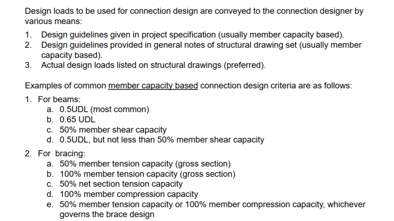
 
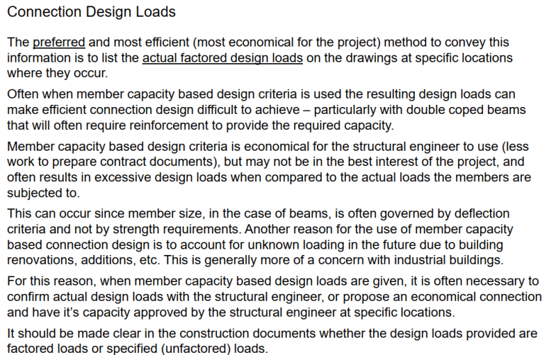
Here's a slide from a connections course I took a few years back. This course was in the context of the Canadian market but should be applicable to NA generally. For those unfamiliar with Canada we only have Limit States Design (same as your LRFD) so ASD vs LRFD is not usually a thing here in this context.

Capture_ii8jy9.png


Capture2_poe2bf.png
 
For about 90% of connections I design, Items 1a and 2a are most common. I still get the odd clown that specs full section capacity.

-----*****-----
So strange to see the singularity approaching while the entire planet is rapidly turning into a hellscape. -John Coates

-Dik
 
Mend your ways, O funny one... From a project of a couple of days back... it happens often... too often.

Clipboard01_adznw4.jpg


and my approach in my shop drawing connection design is as follows (for the same project). I spec the beam spans where there are multiple spans for the same beam. The W14x30 in one instance has a 4' span.

Clipboard01_zqvsbc.jpg


-----*****-----
So strange to see the singularity approaching while the entire planet is rapidly turning into a hellscape. -John Coates

-Dik
 
Is it really that hard to put the design force (moment,shear etc) for each connection? Even if you try to envelope a worst case for certain types, that may be a bit overkill for some locations but the connection designer will be able to be much more economical.

But in my area it is more common for the EOR to design the connections themselves and let the fabricator send requests to the EOR to change it slightly if it has savings. Then the EOR can confirm or deny.
 
If you can use a simple means of denoting design reactions, like max UDL it solves a lot of problems and work for projects that are forever being 'pushed against a wall' for budget. You may have 1000 members, and do you limit it to shear? Why not moment and axial load. The more information you show, the greater your liability, generally. The added information just tends to clutter up the drawings. The example was from my 1007th project from my current employer in the last 3 years... most are small.

It's just the odd flyer, like my example, that shows the EOR put little thought into stipulating the design loading.

-----*****-----
So strange to see the singularity approaching while the entire planet is rapidly turning into a hellscape. -John Coates

-Dik
 

For shear, use a connection rule (like 50% UDL).
For short beams, provide shear on drawings.
For moment connections, provide shear and moment on drawings.
 
For short beams, I stipulate the design span, as I noted in my example above.

-----*****-----
So strange to see the singularity approaching while the entire planet is rapidly turning into a hellscape. -John Coates

-Dik
 
I often try to just make a short table that says something like the below (but formatted more clearly). It's pretty easy to make a table of a small handful of member types for most projects without it getting too complicated, and the design force can normally be "Force that results in a reasonably conventional connection that I quickly screened my design against" rather than a huge analytical pain. I'll just list 80% of the design force you can get with a 3 bolt clip angle or whatever is reasonable. You can go into as little or as much detail as you want. I've done it entirely by beam depth, done it by depth and weight, and done it by depth, weight and span ranges. Then you just specifically call out the two or three places where it's exceeded.

I've considered making a master table and putting it on a standard drawing, but it hasn't seemed worthwhile.

Working in industrial stuff, I'd be way happier if everyone put explicit connection force tables on their drawings so you know what you can rely on 15 years later when you're putting 30% more weight on the thing.

---

Connections for the following beam types shall be designed to the factored forces below except where noted otherwise:

Shear Connections
W200 Strong Axis = 100kN
W310 Strong Axis = 200kN

Moment Connections:
Where designated with the tag "M.C.", connections for the following beam types shall be designed to the factored moments below. Moment Forces below are in addition to the Shear Forces shown above.

W200 Strong Axis = 50kNm, Weak Axis = 15kNm
W310 Strong Axis = 100kNm, Weak Axis = 20kNm

Bracing Connections:
L152x152x6.4 = 70kN Tension or Compression

 
I have an excel spreadsheet that you load the AISC beam size and the span... and it does all the work.

-----*****-----
So strange to see the singularity approaching while the entire planet is rapidly turning into a hellscape. -John Coates

-Dik
 
Status
Not open for further replies.

Part and Inventory Search

Sponsor