Continue to Site

Eng-Tips is the largest engineering community on the Internet

Intelligent Work Forums for Engineering Professionals

  • Congratulations SSS148 on being selected by the Eng-Tips community for having the most helpful posts in the forums last week. Way to Go!

Moment connection WF beam to HSS 1

Status
Not open for further replies.

RabitPete

Structural
Nov 24, 2020
109
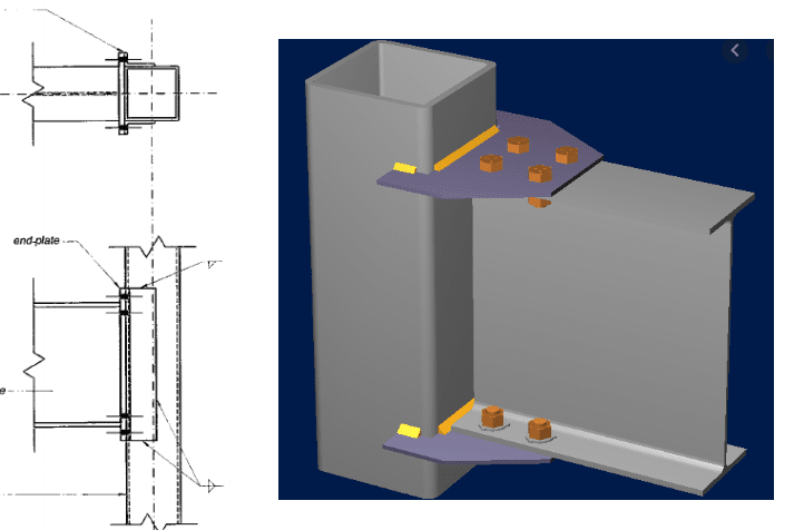
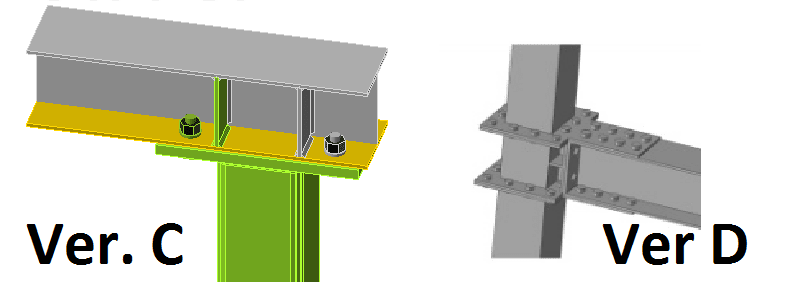
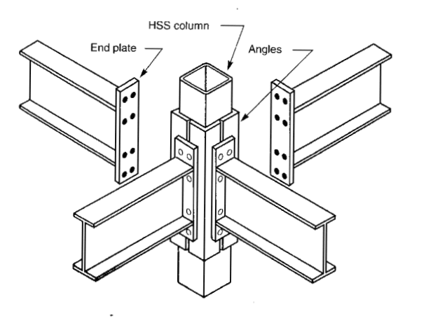
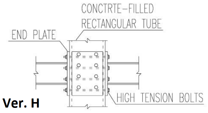
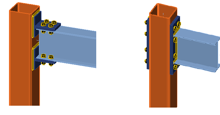
Any recommendations/references on how to calculate capacity for one of the connections pictured below or any better ways to design a connection between 6 x 6 x 1/4 HSS column and W6-15 beam for a full moment? With a beam height of only 6" and only a couple inches to spare under the beam, the best solution I found so far was a column with an end plate and a beam bolted on top of it, but it is still no match for a full moment capacity of the column.
connect_bg0g1x.png
 
Replies continue below

Recommended for you

I prefer the option on the left mainly because it avoids having a push/pull force acting on the most flexible part of the HSS. It vaguely reminds me of some of the highway sign structure connections in AASHTO, which (from memory) use a kind of stiffened box welded around the hollow vertical member with a plate for bolting on the mast arm.
 
At least i would try this option: the bolted connection with end plate and the nuts welded into hollow section wall.
The holes drilled in the HSS large enough for the nut dia. then the nut is welded to the stell section flush with the outside surface of HSS. However, the HSS thickness 1/4 in. could be a question..


Nuts_welded_to_HSS_mv6lzq.png
 
HTURKAK said:
At least i would try this option: the bolted connection with end plate and the nuts welded into hollow section wall.
The holes drilled in the HSS large enough for the nut dia. then the nut is welded to the stell section flush with the outside surface of HSS. However, the HSS thickness 1/4 in. could be a question..
It's a very neat looking solution, but I doubt it would develop enough moment strength. You would need something to transfer the load to the side walls and preferably to the opposite side as well. e.g. something with diaphragm all around like version D pictured below. Version C is what gave me the highest moment capacity so far, but still short of what I would like it to be
connect1_kvqca6.png
 
RabitPete said:
...still no match for a full moment capacity of the column

Depending on the grade of your HSS, it is at least 18% stronger in bending than the beam...so you'll never get this connection to work for the column bending capacity, you should be working the beam capacity.

Your "version C" should be able to be made to work with enough stiffeners around the bolts in the beam flange and a thick enough cap plate. You may need a doubler plate on the bottom flange if the flange bending is too much even with stiffeners.

I would probably try to make the following work:

[ul]
[li]Cap plate on the HSS column that extends out and serves as a top flange plate for the beam - this engages the full HSS with the top flange force[/li]
[li]Single shear tab welded to HSS bolted to beam web[/li]
[li]At the bottom of the beam wrap around plates welded to the HSS and bolted to beam flange - similar to your version D, except I'm not sure what the bolts are doing around the perimeter of the HSS[/li]
[/ul]
 

I agree with you for this set up .... the connection could be classified semi rigid for 1/4 in thk rather than rigid connection . However, you may develop full moment connection with using doubler plate ( thick shim plate ) welded all around to the HSS ..


I'm not keen on welding nuts... don't even like to on anchor rods.

Rather than think climate change and the corona virus as science, think of it as the wrath of God. Feel any better?

-Dik
 
How much of a moment? and can you have the beam sitting on the top of the column?

Rather than think climate change and the corona virus as science, think of it as the wrath of God. Feel any better?

-Dik
 
CANPRO said:
Depending on the grade of your HSS, it is at least 18% stronger in bending than the beam
Looks like other way around: 36.5 kip-ft for the beam and 32.9 kip-ft for the column (Sx= 9.72 for W6x15 & 9.54 for HSS6x6x1/4, 50ksi for the A992 & 46ksi for A500B, ϕ=0.9)

I've considered a cap plate with a shear tab before, HSS obviously fails near bottom moment plate, so it will need to be wrapped around the column. However I could not find any reference in AISC on how to actually calculate this type of connection.
verE_p7mjl3.png
 
dik said:
How much of a moment? and can you have the beam sitting on the top of the column
Required design resistance is 25 kip-ft which is 76% of what column can handle (33 kip-ft)
Beam can sit on top of the column (ver C) but it is not ideal, as there is another beam connects orthogonally to it (shear connection) and it will look really weird if another shear tab is added in between stiffeners to the Ver C.
 
Instead of plate stiffeners in Version C, could use half HSS each side of beam web.

BA
 
CONS

1) Not the cheapest option.
2) Clumsier for shipping and handling.
3) You really want your beam flanges wider than your column for this.

PROS

4) About as strong as you're likely to make something like this.
5) About as stiff as you're likely to make something like this.
6) Fairly erection friendly.

J01_a69cm7.jpg
 
Half HSS is a great idea, looks better, easier to fab and erect, and as an additional bonus, cross beams don't need to be coped.
I did think of a solution by "KootK", however top of the beam needs to be flush, cant have those bolts sticking out.

How about a concrete filed column? 6" should be large enough to bolt from the inside and then it can be filled with concrete after erection.

verH_pubjxd.png
 
Can you do something like this?

image_fmtdzo.png


Rather than think climate change and the corona virus as science, think of it as the wrath of God. Feel any better?

-Dik
 
How about cover plates on both sides of the HSS (since the widths are the same) and either bolts to angles (similar to Sideplate) or welds to the toes of the beam flange?
 
I'd just shop weld (or bolt?) a monster-thick clip angle to the top and bottom of the W, then full-around (field?) weld angles to the box face and depend on the angle's thickness to not allow angle or box face to bend and thereby distribute all W6's flange force across the entire face of the box and into "webs", or side walls of the HSS. Not happy? Use thicker angles.

| <-Face of box
|
|| <- "thick" angle, 6" long
||___
|===============
| W6
|===============
||---
|| <- "thick" angle, 6" long
|
|
| <-Face of box
|

 
Regarding Ver. C: I assume replacing individual transverse stiffeners with HSS halves would also serve as web doublers and take care of the panel zone shear limitation, right?

Regarding Ver. H: Any examples and/or code references on how to calculate capacity of the HSS with through-bolts? This version would be ideal, and concrete fill is also desirable.
 
Thanks everyone to for the input. I gave up trying to find an analytical solution right out of the code box and ended up using FEM based tool (Idea Statica connection). Version with through bolts achieved 95% of the column moment capacity based on AISC 20mrad criteria (even without concrete fill) while welded T cleat was at 87%. Probably due to bolts with stiffener utilizing both sides of the column and distributing loads between them evenly. It is also more erection friendly but not as pretty. Always a trade off, is not it?

conn_jgwpiq.png
 

The version with through bolts seems more erection friendly but is it looking neat ? .. Still do not know the reason for 'full' moment capacity.. If i were in your shoes, i would try 'semi rigid ' connection with the assumption of simple architectural bldg and aesthetic concerns..
 
Status
Not open for further replies.

Part and Inventory Search

Sponsor