Continue to Site

Eng-Tips is the largest engineering community on the Internet

Intelligent Work Forums for Engineering Professionals

  • Congratulations KootK on being selected by the Eng-Tips community for having the most helpful posts in the forums last week. Way to Go!

Moment Connection with SHS Column 2

Status
Not open for further replies.

TekEngr

Civil/Environmental
Feb 4, 2012
148
Please review the moment connection and suggest this scheme is reasonable to transfer the 250 KN-m moment each side into the SHS column
Please also suggest the SHS column wall thickness is 10 mm is enough against bending for 250 KN-m Moment.
any excel sheet or software to design this type of connection ?

Regard's
Ammar
 
 http://files.engineering.com/getfile.aspx?folder=60188905-01b5-4df0-b50a-fcef51653588&file=cONNECTION_PLATE_DETAIL_NEW.pdf
Replies continue below

Recommended for you

Interesting configuration. I think that the stiffeners on the column will be problematic. They'll tend to plastify the tube walls locally.

I like to debate structural engineering theory -- a lot. If I challenge you on something, know that I'm doing so because I respect your opinion enough to either change it or adopt it.
 
Another option might be to pass the beam stub through the column and use segments of SHS as stiffeners. It would be more expensive though and you'd want your beam flanges wider than your column.

I like to debate structural engineering theory -- a lot. If I challenge you on something, know that I'm doing so because I respect your opinion enough to either change it or adopt it.
 
Calculate the couple force resulting from the moment in each flange, and simply check D.G 24 chapter 7 checks, and for the shear, it will affect the web only check the shear tab punching check for the HSS from the same reference above.

the stiffener u added will not do u any good, i think you will have to use a thicker SHS thickness at the connection location.

I am assuming your using the AISC code.


ôIf you don't build your dream someone will hire you to help build theirs.ö

Tony A. Gaskins Jr.
 
I am using British code. Any reference from British code to check the SHS local buckling?
My SHS column is failing in local buckling due to the large moment (250 KN-m each side of column), so how we can increase the local buckling capacity of column, any suggestion?
If I weld the 6mm plate on all 4 sided of column at connection location only then what you think it will increase the buckling capacity of the column?
And second option in my mind is that to use the thicker SHS section at connection location but I am confused how I will splice the column from top and bottom and it is also a difficult fabrication?
Which option is better please suggest.
 
Is it possible to provide vertical bracing? I'm not used to using HSS sections but usually if I have to use a particular beam, the only possible outcome would be to use bracing to eliminate the moment on the beam.
 
@ Leftwow.....no we cant use bracing because we have the full block wall under the beam .
any other solution ??
 
I don`t recommend using a 6mm plate on the wall, it will not work with the SHS wall at the tension flange, the easiest solution is to use a thicker SHS wall thickness at the connection location, splice it with a full penetration weld and backing bar.


ôIf you don't build your dream someone will hire you to help build theirs.ö

Tony A. Gaskins Jr.
 
Awesome doc ameyerrenke!

I like to debate structural engineering theory -- a lot. If I challenge you on something, know that I'm doing so because I respect your opinion enough to either change it or adopt it.
 
Cidect design guide 5 is for concrete filled holly section columns under static and seismic loading. You fill the beam up with concrete and rebar... no more localized buckling!
 
I was typing as KootK posted on 9DEC15, 14:19, and when I saw his post I quit typing because he said essentially what I was going to say. But, it seems like this relatively clean detail went right over everyone’s head, in favor of more complicated details. Use your end pl. moment connection, but use a 2 or 3' long stub of a WF beam with wider flanges than the HSS width, but the same depth of the rest of the beam string. I don’t understand why you need six small triangular stiffeners on the end pl. on the stub, at the stub web, and then not on the longer beam at that same moment location. Explain. If you use a heavier WF stub which is 5, 6, or 7' long your moment will be lesser in demand. This WF stub is welded to the top of the lower column. The next column up has a moment capable base pl. bolted or welded to the top of the WF stub. Cut a length of the same HSS tube with such length that it fits btwn. the inside of the WF stub flanges vertically. Then rip this short section of HSS tube so that the two halves match the outside widths of the columns above and below, and fit into the WF stub web on both sides. In effect, you will rip out some HSS web material to match the WF stub web thickness. Clip the HSS webs to fit around the radius at the flg./web ‘k’ area’ on the WF stub, and don’t weld into these corners. The bottom column now forms a “T” and is all shop fab’ed. This gives you beam and column continuity with relatively clean detailing.
 
Thanks for the plug dhengr. Try not to be miffed if my sketch blows up your browser. I don't know how to fix that on my end and I refuse to give up in thread graphics. Let's blame the site developers. Filthy weasels.

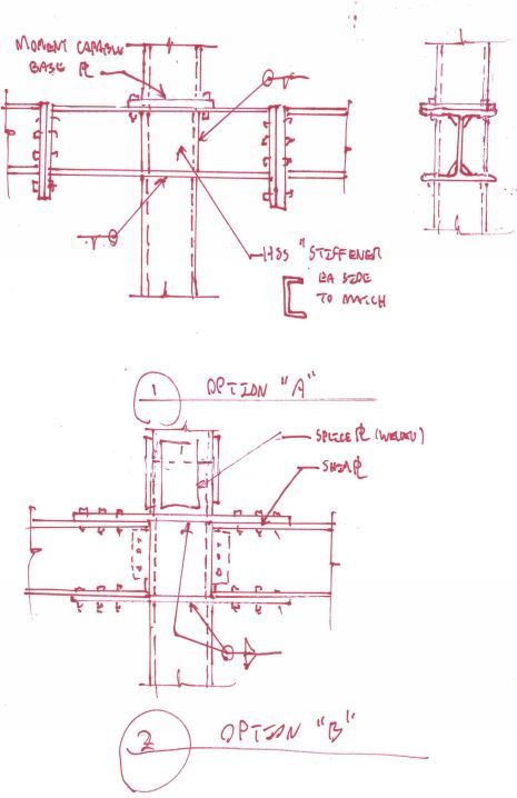
The sketch below shows the option that dhengr and I have been proselytizing about. I've also included a second option. I would consider both to be high demand solutions. If you can get the numbers to work on some of your earlier proposals, they may well be cheaper to fabricate. Now that I look at it, my #2 was actually included in ameyerrenke's doc. I'm not sure that it has any advantages over the bypass solution though other than, perhaps, space savings.

Capture_yayfox.jpg


I like to debate structural engineering theory -- a lot. If I challenge you on something, know that I'm doing so because I respect your opinion enough to either change it or adopt it.
 
KootK:
Whatever scale you posted your sketches at did not blow my screen sky wide, this time. Keep doing what ever you just did, and report how you did it, for all to see and use. Now, if they would (if they could) put that feature in its own box/window within the thread, and provide a click/button which would allow it to be enlarged for note reading, or some such, and then a second click brings it back to regular viewing size, so as not to screw up the entire thread width, they would really have something. The sizing you just used is large enough to get the point across, and doesn’t cause a bunch of scrolling for every line in the thread. Otherwise, the sketch within the thread feature is a nice feature, and you do a very nice job of using them to help explain what you are trying to convey.
 
@ KootK and dhengr ……thanks for your kind suggestions.
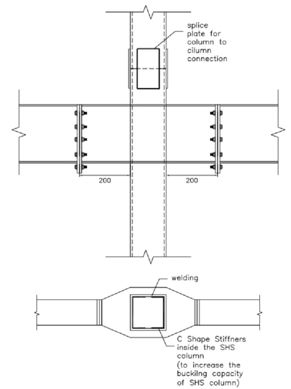
I found the middle way from your option A & B to keep the more simplicity as show below (we need the plane surface on the top because we have the hollow core slab on it and we don’t want any notches in slab)
I have still following doubts regarding this please clarified so I can finalize this connection.
Does the inside 'C' shape stiffeners will provide enough resistance against buckling; however we cannot weld this stiffeners all-around because of space limitations? Can we use simple plate stiffeners instead of C shape stiffeners inside the column wall to wall at connection location or for more simple fabrication can I weld the plates outside wall SHS column for increasing the thickness of the section ?
The moment connection plate of the stub and main beam will be design with normal checks or need some additional checks to design this kind of plate?
I am keeping the stub length as minimum as I can keep (200 mm long) because the moment will be more with large lever arm what do you think about it?
[
modified_stub_connection_an6zqm.jpg


You've misinterpreted option one. Please review my sketch again. The beam passes through, not around, the column. The column stops below the beam and resumes above it.

My understanding has been that your bolted connection is a moment connection. If that's the case, then your negative moments should be highest closest to the column. I imagine that you'll want to keep your beam stub fairly short for shipping though.

I like to debate structural engineering theory -- a lot. If I challenge you on something, know that I'm doing so because I respect your opinion enough to either change it or adopt it.
 
Status
Not open for further replies.

Part and Inventory Search

Sponsor