Eng-Tips is the largest engineering community on the Internet

Intelligent Work Forums for Engineering Professionals

  • Congratulations waross on being selected by the Tek-Tips community for having the most helpful posts in the forums last week. Way to Go!

Moment discrepancy on bridge columns for piers with same span 2

Status
Not open for further replies.

Jean_Wong

Structural
Sep 8, 2016
29
0
0
PH
Capture_fy1muw.jpg


Good Day!

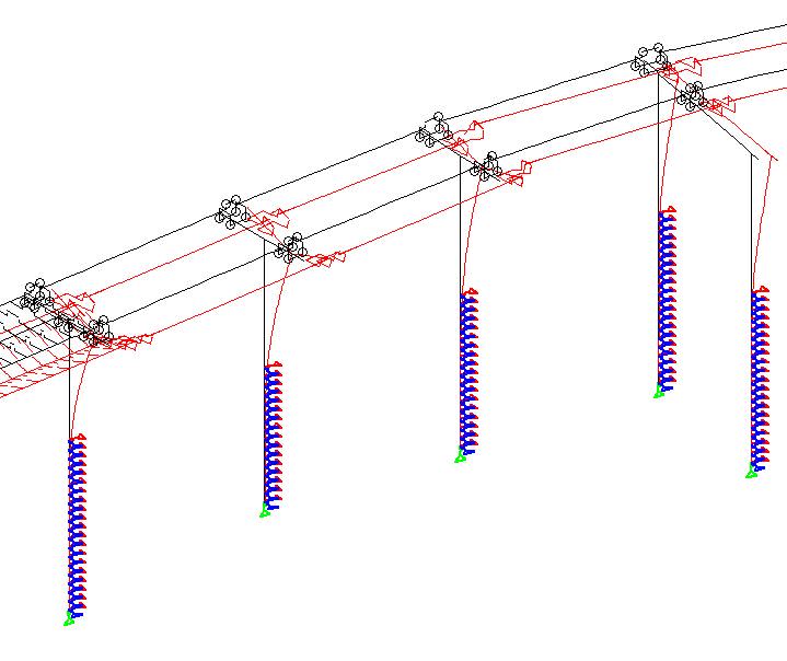
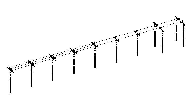
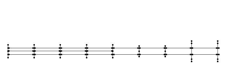
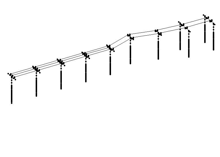
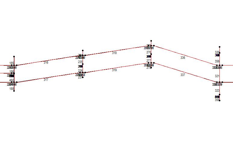
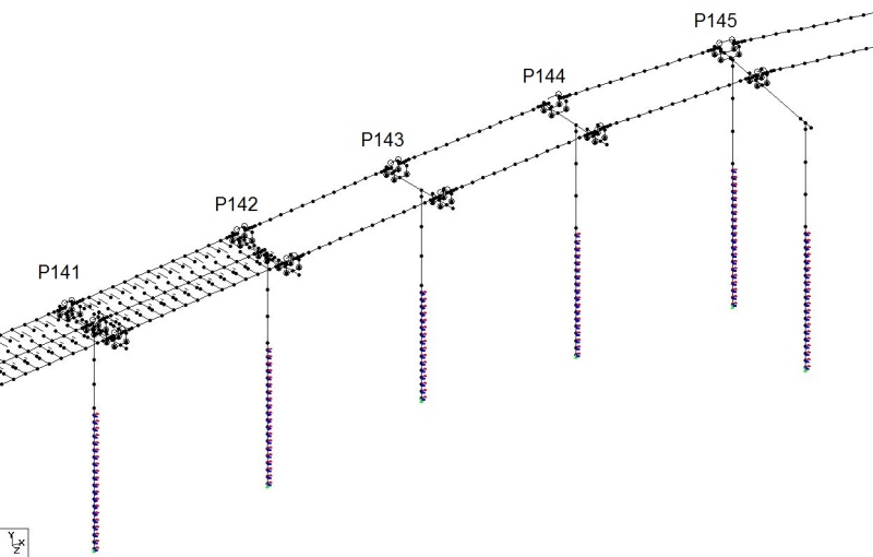
I am designing a 13-span curved bridge for railway, part of which is shown in the image uploaded. The members between piers in the image are the girders. Piers P142 and before support a pocket track which is why there are 3 girders. P143 onwards only support 2 girders. These are prestressed box girders.

P143 and P144 support the same type of girder, same span. P143 column is 12.7m high while P144 column is 13.6m high. Material properties are the same, column is circular with 2.2m diameter and piles are 2.8m diameter. The only major difference is the piers next to P143 and P144. As stated before, P142 is a pocket track which has 3 girders. However, P145 is a portal, which is supported by 2 columns. Also, P144 is fixed on preceding girder and expansion on succeeding girder.

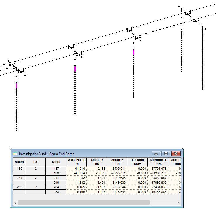
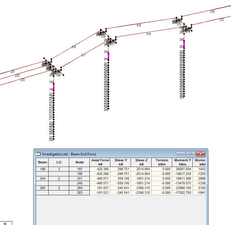
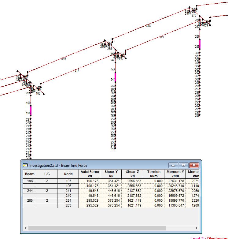
When checking Strength1 axial load at the bottom of each column for P143 and P144, they are almost the same at 13000 kN.

But there is a huge difference in TRANSVERSE EARTHQUAKE MOMENTS for columns at P143 and P144. P143 column has a 35000 kN-m moment while P144 only has 22500 kN-m. When checking columns adjacent to said piers, P142 has 38000 kN-m and P145 has 14000 & 17000 kN-m for left and right columns.

Is this normal?

I am assuming that because P143 is next to P142 which is a pocket track, some of the forces from P142 is transferred to P143. On the other hand, P144 is next to a portal pier and also has expansion releases for that span which is why most forces from girder are carried by the portal. And the stiffness from the portal also reduces those forces.

But my senior is suggesting that since every parameter for P143 and P144 (span, column height, soil spring, girder, axial load, etc), one of the piers must be wrong and moment values must be close.

What are your opinions?
 
Replies continue below

Recommended for you

I'm guessing you've already spent ample time inspecting all of your inputs, because that is the most likely where the discrepancy lies as your senior engineer stated. Assuming it's not...

One reason why they might be different is perhaps the portal is acting as a moment frame. Under transverse lateral earthquake forces the portal "moment frame" would be a stiff element, so the columns immediately next to it will not deflect as much at the top as columns farther away from it. I.E. P143 will deflect more than P144. If it deflects more than it has a higher moment.

What shoots this theory to pieces is the P145 columns combine for 31000kN-m , and the P142 column has 38000kN-m.

My only other guess is - does the pocket track, with 3 girders, weigh significantly more than the regular track? P143 would be experiencing more forces, since it's closer to the heavier track. But even so, I wouldn't expect it to have 1.5X as much.
 
What direction is this "transverse moment" occurring in? (Based on the X,Y,Z system in the corner of your pic.) It may have something to do with P145 redistributing the load because of its stiffness (relative to the other columns)......or possibly some sort of thrust situation because of the that curve. Hard to say without a model.

Is this in STAAD? Can you post the edit file?

 
Deflection_bqa2ni.jpg


The image above (Piers P142, P143, P144, P145 respectively) shows the deflection for transverse earthquake.
Longitudinal direction is along the bridge while transverse direction is perpendicular to that direction. Both are on the horizontal plane.


STAAD FILE Link
 
After trying to replicate the problem, I have found out that the huge differences in moments originate from the curve. I made 3 similar models with different offsets from the longitudinal axis.

With regards to straight model, the difference between column moments are not too high, especially between the 2 piers supporting 2 girders.

But for the models with offsets, the further the pier column is from the longitudinal axis, the less moment it receives.


What could be the cause of this?
Is this normal or is this a software issue?


Case 1 Straight
3-3_uf8hrb.jpg

3-2_t2t2gw.jpg

3-1_waohei.jpg


Case 2 pier next to pocket track has high offset
1-3_vpjewt.jpg

1-2_chiopc.jpg

1-1_snuivl.jpg


Case 3 pier next to portal has high offset
2-3_xraser.jpg

2-2_snpn3n.jpg

2-1_psxkdy.jpg
 
Thanks.....was able to download it. Looking at it, I suspect it has something to do with P145 being at the peak of that arch (looking at it in plan view; considering the horizontal load). Some sort of arching action may be stopping the pier from seeing the load it should (based on pier stiffness alone). (In other words: the stiffness of it in plan view from the arch formed could be redistributing it (to some degree).)

Arches are a once in a while thing for me.....so I will run some more numbers when I get time today to test my hypothesis.
 
I've messed with it some more and I'm fairly certain the arching action I spoke of in my last post is probably why it's not attracting as much force as you think it should. Put simply: I don't think those piers are stiff enough (whether it's one or two) to have a greater effect on transverse load distribution than the arching action I am seeing.


Status
Not open for further replies.
Back
Top