Continue to Site

Eng-Tips is the largest engineering community on the Internet

Intelligent Work Forums for Engineering Professionals

  • Congratulations SSS148 on being selected by the Eng-Tips community for having the most helpful posts in the forums last week. Way to Go!

Moment of Inertia of Circular Tube Cross Section at an Angle 13

Status
Not open for further replies.

dik

Structural
Apr 13, 2001
26,034
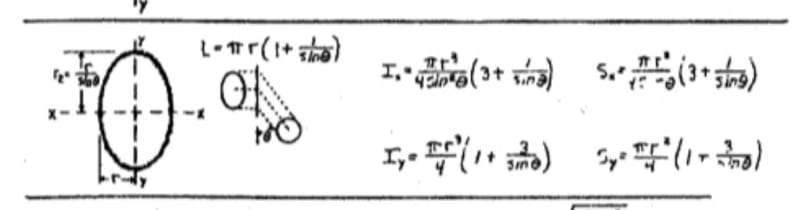
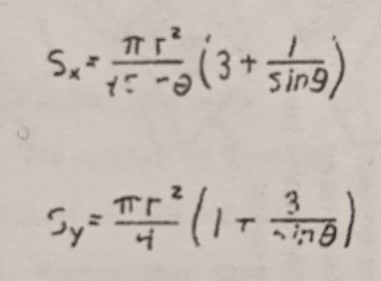
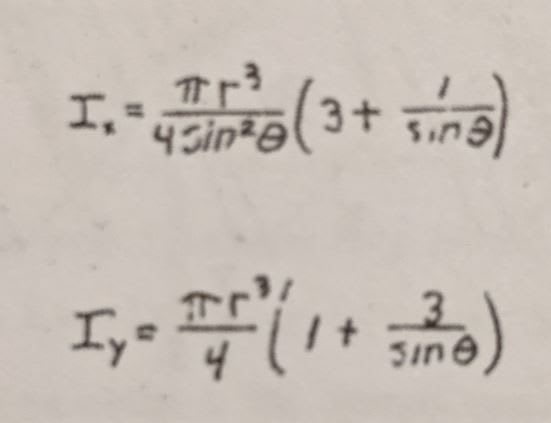
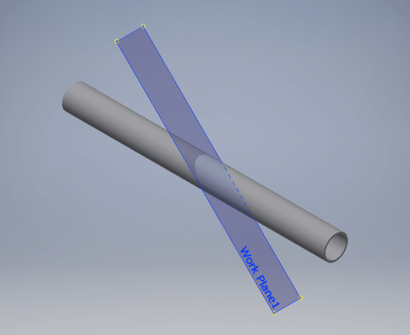
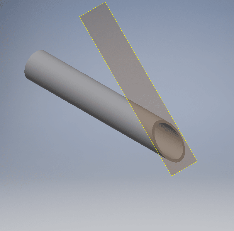
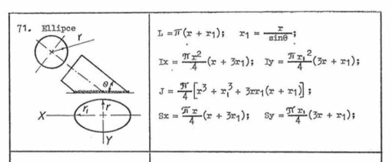
Does anyone have the formula for a circular tube cut at an angle to the axis? I have one for an ellipse, but if I make the major diameter equal to the minor diameter then I get a different number than for a straight circular cross section. They should be similar/exact.

Rather than think climate change and the corona virus as science, think of it as the wrath of God. Feel any better?

-Dik
 
Replies continue below

Recommended for you

You should be using the moment of inertia of a circular ring. That is the section you are considering, even though it is cut at an angle to its axis.

BA
 
As an example, consider if you were doing this to an square tube that you were diagonalizing to a rectangle. I would say that:

1) there would be some "stretch" improvement on the long / web sides but;

2) no improvement on the short / flange sides because pushing on them at an angle would bow them out.

Trying to think about how that pans out for for an ellipse hurts me brain.
 
I'm with BA. The stresses will be distributed in the post as if it's a circle, and that's the stress the weld will see. Because it's cut on angle, you could argue you have more weld per unit length for an equivalent throat size, but I would just ignore that and size it as if it were a flat circle.
 
Blodgett weld as line formula for ellipse.

ellipse_ljrrzi.jpg


Sorry for the fuzzy.

I believe it's from "Solutions to Design of Weldments"


That's how the post is designed (I hope no one thought I was using the elliptical perimeter for the tube design) and the weld checked based on the circular perimeter as well as the elliptical perimeter. I'm aware the elliptical perimeter is a bit off... but not likely significant... the circular perimeter greatly underestimates the weld strengthstress. I just wanted a bit of a handle on where it stood. I didn't mean to imply that I was using the increased section modulus based on the sloped cut. The tube stands by itself, as if it were normal and the weld is similar to that... I just wanted to get an idea of how much greater weld capacity there was if the ellipse were considered instead of the circle.

Thanks gentlemen.

Rather than think climate change and the corona virus as science, think of it as the wrath of God. Feel any better?

-Dik
 
See ROARK`S Formulas for Stress & Strain.

Regards
 
In my note above, I'm assuming you section a tube at an angle, so the thickness normal to the section actually varies as you go around. That's different from laying out a uniform-size weld around the perimter of an ellipse.
That said, my solution for the problem is to just treat it as a circle and figure the elliptical weld is a little stronger, which is quick and easy.
 
... JStephen... as a rough idea I used the Ix using inverse Cos() to get the major diameter with the tube OD as the minor diameter and subtracted this from the Ix using the major and minor diameters +D (I could have used 2xD, but chose the centreline of the weld).

Not exact, but a good ballpark. Thanks... and for small angles, it becomes a better guess.

Rather than think climate change and the corona virus as science, think of it as the wrath of God. Feel any better?

-Dik
 
While my post does not provide the formulas to obtain the inertia of an inclined section of a circular tube, it's an alternative way to obtain the same result. I often use Inventor to calculate inertias of the sections of structural members.

Here's how you could obtain the inertia of an inclined section of a circular tube:

1) Create a tubular part:
2021-05-08_02_10_18-Window_f3yvkt.png


2) Cut the tube using an inclined plane:
2021-05-08_02_13_48-Window_lpploy.png


3) Obtain the inertia using the region properties:
2021-05-08_02_14_35-Window_lr811m.png
 
Thanks... I needed the formulae for an SMath program... done, and I'm happy with it. As the wise ol' owl says, "It's been a hoot." Thanks very much gentlemen. My original formula was in error, and I don't remember the source... and didn't record the source. With 2xD, before modified... and I didn't record the source for this one, either...

image_txwmbz.png


Rather than think climate change and the corona virus as science, think of it as the wrath of God. Feel any better?

-Dik
 
My section properties spreadsheet will do a hollow ellipse:

Hollow_ellipse_tyke7b.jpg


The example has the long axis set to root 2 x the short axis, with the inner ellipse with a radius 2 units shorter on both axes.

The observant will note that the results suggest that Iy = Ix = Ixc, which is obviously wrong. Since the origin is at the centroid of both ellipses Ix = Ixc and Iy = Iyc. I will fix that and upload to the same address.

Doug Jenkins
Interactive Design Services
 
While it is true that the thickness of a circular tube varies when cut at an angle, the weld material should be of constant size. So the formula could be based on an elliptical line element corresponding to the outer dimension of the section.

BA
 
Yup that's how the formula treats it... I've modified that by using D rather than 2xD... to reduce the capacity by a tad... the added perimeter over the straight circular section with the full D, works, too. Thanks for everyone's help...

Rather than think climate change and the corona virus as science, think of it as the wrath of God. Feel any better?

-Dik
 
Some caution is warranted if the angle θ between the cut plane and the member axis is small. A fillet weld will not engage much metal at the toe and may be hard to access at the heel.

BA
 
BAretired: That's why fillet welds are not pre-qualified with a dihedral angle less than 60 degrees. See W59 figure 4.8 for example or equivalent in AWS. Once you have less than 60 degrees (or more than 135) the weld is no longer considered a fillet and must be specified as a partial penetration groove weld or like with effective throat clearly specified.

For raker design (HSS tubes connected to flat plates top and bottom on a 45 degree angle) we show a cut section on our drawings through the joint so it can be clearly seen where a fillet stops and a partial penetration weld begins. Typically we indicate the effective throat required on the small angle side, and the desired fillet weld on the larger angle side. On plan we indicate this via different line thicknesses.
 
....“it's to accommodate guardrails welded on a slope”.

@ dik. Please, can you tell us the tube diameter and the design loads?

Regards
 
Very often the 1.66x0.125 is the guard post of choice and sometimes the 0.140 wall thickness (properties for the 0.191 wall thickness are shown).

image_a4cgva.png


and design loads (the data columns line up... just from different parts of the program):

image_tf2ag7.png


Rather than think climate change and the corona virus as science, think of it as the wrath of God. Feel any better?

-Dik
 
Enable said:
BAretired: That's why fillet welds are not pre-qualified with a dihedral angle less than 60 degrees. See W59 figure 4.8 for example or equivalent in AWS. Once you have less than 60 degrees (or more than 135) the weld is no longer considered a fillet and must be specified as a partial penetration groove weld or like with effective throat clearly specified.

That's good information. So in this case, the minimum angle between member axis and cut plane would be 45 degrees if a fillet weld is to be used.

BA
 
Status
Not open for further replies.

Part and Inventory Search

Sponsor