Continue to Site

Eng-Tips is the largest engineering community on the Internet

Intelligent Work Forums for Engineering Professionals

  • Congratulations KootK on being selected by the Eng-Tips community for having the most helpful posts in the forums last week. Way to Go!

Moment or Pin 5

Status
Not open for further replies.

MegaStructures

Structural
Sep 26, 2019
366
Would you consider this a moment connection, or pinned connection if the following is true:

1. The connection between the HSS and I-beam is a direct weld (rather than a bolted cap plate as shown)
2. Instead of a continuous beam this is at a "corner" where two beams frame into each-other at a 90° angle and are welded together at the flanges

If not, would you then consider it a moment connection if there were a gusset plate welded to the HSS and bottom flange of the I-beam?
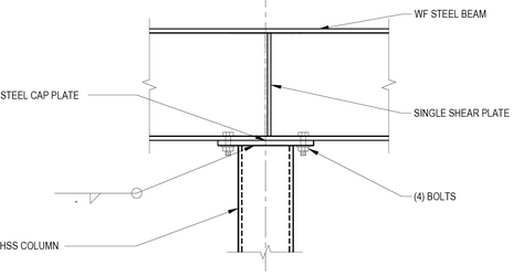
HSS_Cap_Plate_kg9mpn.png


Edit: Of course there will be moment transferred by the HSS end connection, so I am asking about the rotational limit of the I-beams

“Any idiot can build a bridge that stands, but it takes an engineer to build a bridge that barely stands.”
 
Replies continue below

Recommended for you

I'm a believer in the Zen approach to this, "It is what you want it to be." I'd prefer pinned, but if you want, design it as a moment connection, just make sure the connection and HSS can take the moment. Of course, you need to be consistent.
As far as the wide flange beam, it would look like a more official moment connection if the stiffeners aligned with the bolts, but I don't think it would act much different unless the moment was huge.
 
I'd treat it as a pin... using Feldberg's concept that without stability issues, if you make any part of the steel structure stronger, you do not diminish the overall strength... I always add plate stiffeners over columns with continuous beams... and cut the plate stiffener back an inch or so at the top (easier to fit). Even if not needed, adding the stiffener causes the section to maintain its section strength beyond yield. Hopefully not needed but it provides redistribution.

Rather than think climate change and the corona virus as science, think of it as the wrath of God. Feel any better?

-Dik
 
Treating it as a pin might be an unconservative assumption for the column as you'd be ignoring some bending moment that will be there. The connection isn't near an ideal pin or fixed condition, so clearly it is semi-rigid. It depends how far you want to take the design in terms of estimating the rigidity of the connection - in these cases I design the column assuming it is a fixed connection.
 
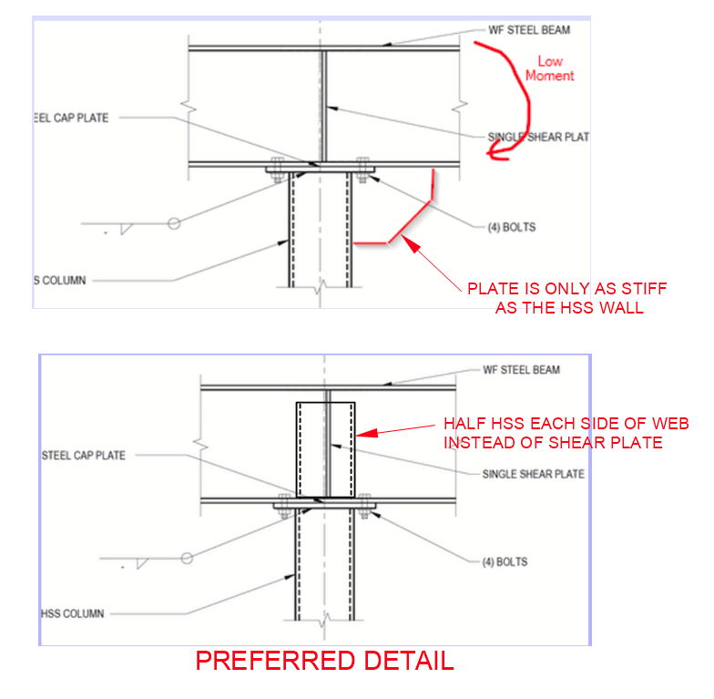
Half of an HSS each side of the web instead of the single shear plate would improve the connection considerably. Increasing cap plate thickness would improve it more. That would make it a pretty decent moment connection. If four bolts is enough, I prefer them over field welding.

BA
 
Similar to what CANPRO posted, I'd say the model assumption depends on what you're checking. As with almost any connection, the reality is somewhere in between fixed and pinned. When faced with any semi-rigid connection where critical reactions could be generated with either assumption, I usually take the easy way out and do both, and use the worst results from either assumption, an envelope approach, if you will.

Rod Smith, P.E., The artist formerly known as HotRod10
 
As above. Take a semi-rigid approach and check both cases.

Treating it as a pin can be quite unconservative for the column and in reality this will be closer to a moment connection that a pin.
 
I would say it is a pin connection with limited moment capacity. In the past, the column was designed for the maximum axial load with a code specified "minimum eccentricity" to ensure the column has a minimum moment capacity (some people conservatively take half of the column width as the minimum eccentricity). In reality, the column will experience bending when one side of bolts are in tension, which is the result of uneven loadings that causes reverse curvature of the beam, at this stage, the compression load on the column is much less than the load applied in design, so the moment.
 
r13 said:
I would say it is a pin connection with limited moment capacity.
I would suggest you are dangerously mixing terms there. (Not to mention that the description is an oxymoron)

Pin, semi-rigid, moment connection describe the STIFFNESS behavior of the connection. They don't explicitly describe the capacity of the connection.

I've seen severe column bending due to connections like this. To the extent that it exceeded code serviceability requirements and was very noticeable visually. Significant rectification works were require all because the engineer call this type of connection a pin. The stiffness of the connection matters especially if your column is 'slender' and your beam rotation at the support is 'high'. Notice that none of the above conditions are directly related to capacity. So your beam and column could have plenty of capacity but you still end up with an unserviceable condition for your column.

*Note: I'm not saying that all modelling of 'cap plates' as pins is necessarily a problem. But you shouldn't do it blindly which is why checking your assumptions is important.
There are plenty of papers written on this matter.

**Additional: Even checking the two extremes of pinned/rigid doesn't completely cover yourself. Sometime you should model for semi rigid. That said I've never done so except as an academic excursion.
 
human909,

Yes, I admit my statement is confusing. What I meant really is simple - obtain the maximum possible axial load by fully load the adjacent spans, then get column design moment by placing the axial load with minimum eccentricity (or 1/2 column width). The structural analysis will then be carried out with pinned assumption. That's the reason I was reluctant to call it a semi-rigid connection, since no moment is specified, nor rotational spring is attached at this stage, but would add on a later time for verification purpose only, if necessary. Once the design is complete, and all details (bolts, plate) are determined, then, yes, physically it is a "semi-rigid" connection.
 
r13 said:
human909,

Yes, I admit my statement is confusing. What I meant really is simple - obtain the maximum possible axial load by fully load the adjacent spans, then get column design moment by placing the axial load with minimum eccentricity (or 1/2 column width). The structural analysis will then be carried out with pinned assumption. That's the reason I was reluctant to call it a semi-rigid connection, since no moment is specified, nor rotational spring is attached at this stage, but would add on a later time for verification purpose only, if necessary. Once the design is complete, and all details (bolts, plate) are determined, then, yes, physically it is a "semi-rigid" connection.

Sorry to jump on that. You approach outlined above seems sufficiently conservative for most reasonable scenarios.
 
human909,

Thanks for understanding.
 
Conservatively assume as a pinned connection - why is it conservative? Imagine a rigid frame with a pinned base. Gradually add UDL weight on the beam. Once the end moments of the beam goes beyond the moment capacity of the joint, the rigid beam/col joint yields and becomes a pin connection. Moment diagram of the beam changes to that of a simple beam, 0 moment capacity at ends, a pin will develop at mid-point of the beam once bending moment exceed capacity and the beam starts to collapse.

The joint obviously has a small moment capacity (determined by localised failure, load path for the beam flange tension/compression forces being transfered to the relevant column flanges), which I would only utilise when required (i.e. no bracing elements/portal frame action is required for stability, beam struggling to work when analysed as a simple beam).
 
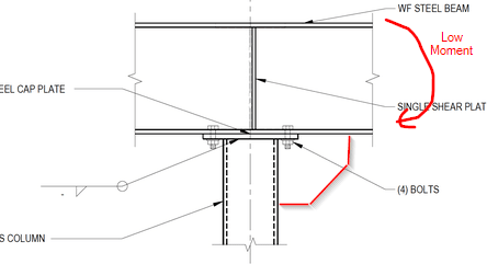
Thank you all for the valuable input. The moment redistribution approach recommended by Enhineyero and dik makes a lot of sense. In some places I need a moment connection for lateral stability; in those locations I added a large "in-plane" stiffener plate. With low moments I suspect there will be no yielding of the HSS and the connection will remain relatively stiff.

Moment_Plate_ejew14.png


“Any idiot can build a bridge that stands, but it takes an engineer to build a bridge that barely stands.”
 
I certainly appreciate there is more than 1 reasonable approach to any particular design, but I feel like a lot of the reasoning above is missing the mark a bit.

Enhineyero said:
Once the end moments of the beam goes beyond the moment capacity of the joint, the rigid beam/col joint yields and becomes a pin connection

Thats good news for the beam, and I agree it is conservative for the beam. But the concern listed by me, human909, and BridgeSmith isn't about the beam, its about the column. Where do the end moments from the beam go? To the column!

The last time I took a close look at this I was designing a typical warehouse roof - relatively long girder spans and tall columns. In this case I designed the roof beams assuming the connection in question was a pin. For the columns, even a small bit of fixity in that connection will drive a concentrated moment into the top of the column. That moment causes some lateral displacement in the column, which can become significant once you start considering p-delta effects with large axial loads.

human909 said:
Pin, semi-rigid, moment connection describe the STIFFNESS behavior of the connection. They don't explicitly describe the capacity of the connection.

Thank you human909, I find it a bit shocking how many engineers don't understand this concept. A connection can be extremely stiff and relatively weak. Connection stiffness is what attracts load, the connection strength has to be adequate to transfer the forces that the stiffness attracts.
 
CANPRO said:
hats good news for the beam, and I agree it is conservative for the beam. But the concern listed by me, human909, and BridgeSmith isn't about the beam, its about the column. Where do the end moments from the beam go? To the column!

I see the concern here, treating the column as pinned from the jump won't account for lateral displacement to the top of the column in the process of yielding the steel and "getting to" a pinned connection. Also it is possible that a buckling mode could occur at stresses below the yielding point and the member could never have a chance to redistribute moments and become a pinned connection.

“Any idiot can build a bridge that stands, but it takes an engineer to build a bridge that barely stands.”
 
Also keep in mind that the moment doesn't just disappear once the connection yields. If the connection goes plastic after transferring 20 kN-m to the column, then that 20 kN-m is still in the column after the connection yields...it just can't transfer any more moment beyond that point.
 
CANPRO said:
Thats good news for the beam, and I agree it is conservative for the beam. But the concern listed by me, human909, and BridgeSmith isn't about the beam, its about the column. Where do the end moments from the beam go? To the column!
Thanks for jumping in CANPRO. I did have a reply to Enhineyero typed up suggesting similar, but I got sick of sounding like a broken record in this thread.

It is relatively easy to show a scenario where the column satisfies strength requirements when the connection is a pin, but fails when the connection is a semi-rigid connection. And you don't need a 'strong' moment connection to result in this. I did have a play around with this. Though in most scenarios IF you include load eccentricity then it will cover you. But as previously described my preference is to check the column assuming a moment connection.

CANPRO said:
The last time I took a close look at this I was designing a typical warehouse roof - relatively long girder spans and tall columns. In this case I designed the roof beams assuming the connection in question was a pin. For the columns, even a small bit of fixity in that connection will drive a concentrated moment into the top of the column. That moment causes some lateral displacement in the column, which can become significant once you start considering p-delta effects with large axial loads.
That is exactly the scenario where I first encountered issues with this, though in that case I wasn't the involved in the design, I just saw the results on the columns.

As said in a previous thread on the topic. If you NEED your connection to behave like a pin then design it like a pin, this is especially true for columns.
 
HSS walls are usually pretty thin. Comparing the two details below, I much prefer the lower one. The stiffeners do not necessarily have to extend all the way to the top flange, which makes it easier to fit. The connection is much stiffer than the upper detail and, I believe, cheaper to fabricate.

image_wrnkpi.png


BA
 
Status
Not open for further replies.

Part and Inventory Search

Sponsor