Continue to Site

Eng-Tips is the largest engineering community on the Internet

Intelligent Work Forums for Engineering Professionals

  • Congratulations KootK on being selected by the Eng-Tips community for having the most helpful posts in the forums last week. Way to Go!

Moment or Pin 5

Status
Not open for further replies.

MegaStructures

Structural
Sep 26, 2019
366
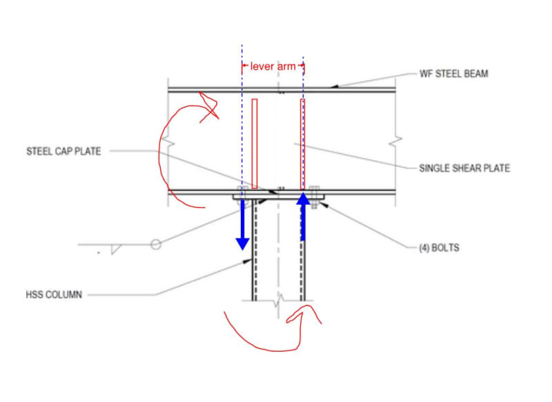
Would you consider this a moment connection, or pinned connection if the following is true:

1. The connection between the HSS and I-beam is a direct weld (rather than a bolted cap plate as shown)
2. Instead of a continuous beam this is at a "corner" where two beams frame into each-other at a 90° angle and are welded together at the flanges

If not, would you then consider it a moment connection if there were a gusset plate welded to the HSS and bottom flange of the I-beam?
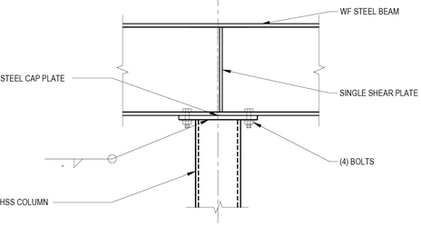
HSS_Cap_Plate_kg9mpn.png


Edit: Of course there will be moment transferred by the HSS end connection, so I am asking about the rotational limit of the I-beams

“Any idiot can build a bridge that stands, but it takes an engineer to build a bridge that barely stands.”
 
Replies continue below

Recommended for you

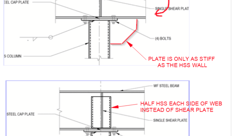
This would normally be my version of BA's preferred detail and, I think, what Jed was alluding too. BA's detail has an advantage in that it includes a solution for support of the beams tying in from the out of plane direction.

OP said:
Edit: Of course there will be moment transferred by the HSS end connection, so I am asking about the rotational limit of the I-beams

Given that this is a deliberate moment connection for a lateral frame, the column will be designed for moment by definition. So little cause for concern there. The question of primary concern, per your comment above, is whether or not the connection is stiff enough to do the very important jobs of:

1) Limiting drift and, therefore;

2) Limiting the potential for a P-Big-Delta collapse.

So, ideally, you'd want the following from the connection:

3) As much stiffness as you can bring to the table without incurring objectionable cost and;

4) A connection for which rotational stiffness can be assessed with reasonable ease.

Treated as an end plate connection, as shown below, you'd not be doing too badly in those dimensions. Welding the column walls directly to the beam flange below the stiffeners would be marvelous in terms of stiffness but many would not deem that a practical connection for erection and cost.

C01_jzdw78.jpg
 
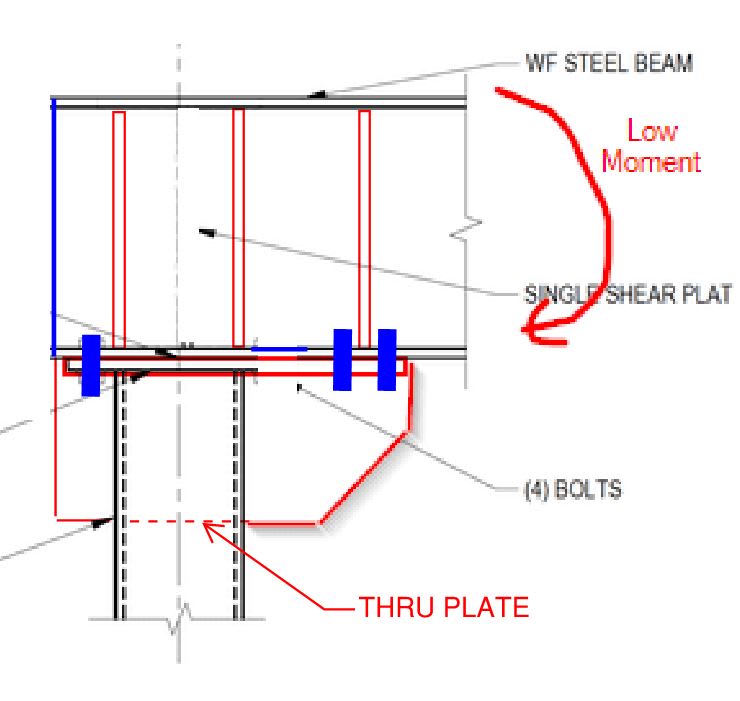
In fifty years, I've never done either of these...
image_gwoy2j.png


Rather than think climate change and the corona virus as science, think of it as the wrath of God. Feel any better?

-Dik
 
I share BA's concern for the flexibility of the column wall against that stiffeners. I've seen solutions like this detailed to solve that problem, sometimes with less stiffeners and sometimes with more.

c02_dr9hli.jpg
 
CANPRO said:
Connection stiffness is what attracts load, the connection strength has to be adequate to transfer the forces that the stiffness attracts.
I always thought this is true for indeterminate structures. Not sure for determinate structures.
 
hoshang said:
I always thought this is true for indeterminate structures. Not sure for determinate structures.

I don't see how whether it's easy or difficult to calculate all the loads traveling through a connection has any effect on the physical reality of how loads pass through said connection.
 
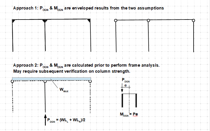
I am going to try to explain the two approaches that make the connection "Semi-Rigid". Why different, both are valid and conservative, the real difference lies in preference of the designer. The first approach is more modern and efficient (in certain sense) due to the advancement in both computing power and software. The second approach predates to the invention of computer. Hope this quells the argument between people in different campus.

image_esvgvq.png


I come up a good phase to distinguish these two approaches: "A Rich Man's Toy vs a Poor Man's Cadillac".
 
@human909, @CanPro - I understand your concerns about the column, However, the approach I take is to look at the element's collapse mechanism.

Lets say that the beam end-moment is high (higher than the bending capacity of the column) and connection was designed to be very rigid as to resist this couple (I find this highly unlikely because localised failure of the column will likely govern the connection design). Connection design usually checks three components 1. localised failure of beam parts (flanges/web) 2. localised failure of column 3. failure of connectors (end-plates, bolts, welding). The weakest of the three governs the capacity of a connection. If you have a small column that cannot resist high bending then this will influence/affect the connection capacity.

The column end yields due to bending, but the column doesn't collapse. I expect the column flanges taking the beam end-moment to gradually yield but once the column flange starts to yield the connection becomes more flexible (due to localised failure of the column component of the connection) and less moment is transferred at the ends.

I can be proven wrong. The behavior I described above is based on theoretical behaviour of steel structures, it is probably best to make a scale model of this and test it, ala mythbusters. I'm a big fan of 'testing' but our industry usually leaves this out to people in the academe. To this I remember the quote "Tell Me and I Forget; Teach Me and I May Remember; Involve Me and I Learn"

 
The trouble with a plastic collapse mechanism is that it must be able to develop without generating any catastrophic / brittle failures en route to that collapse mechanism. And the failure that usually messes that up in steel is buckling, in this case overall column buckling. If the column would buckle as a result of combined flexure and axial load before the connection stops absorbing moment, then it would all be for naught. I do acknowledge that there are practical things that would tend to limit the likelihood of such a failure, including:

1) Inherent connection flexibility.

2) The column's tendency relieve connection moments as flexes.

3) The tendency of a pin-pin designed column to exhibit significant rotational restraint at the top (0.7 < K < 1.0).

4) A column's tendency to shed its flexural stiffness as the axial load imposed upon in approaches the Euler buckling load.

Most of this stuff is difficult to estimate but it is for these reasons that, for many practical beam and column proportions, I will assume the connection to be pinned but moderately eccentric with respect to axial load delivery.
 

Typical cap plate and if moment is required a thicker one... nothing excessive though...

Rather than think climate change and the corona virus as science, think of it as the wrath of God. Feel any better?

-Dik
 
Status
Not open for further replies.

Part and Inventory Search

Sponsor