Continue to Site

Eng-Tips is the largest engineering community on the Internet

Intelligent Work Forums for Engineering Professionals

  • Congratulations KootK on being selected by the Eng-Tips community for having the most helpful posts in the forums last week. Way to Go!

Moment; Reducing lever action in mechanism 1

Status
Not open for further replies.

NoelFa

Automotive
Jun 10, 2024
9
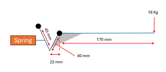
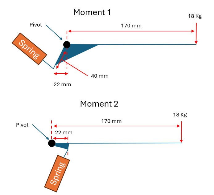
Hi everyone, I'm creating a mechanism to lift a weight and I need to make sure I'm calculating correctly in order to design the correct spring. The first image below shows you my current design, but I have realized that there is a lever action here that could drastically increase the force on my spring. In the moment diagrams I have outlined how I think I can mitigate the lever action by bringing. What I would like is for someone to correct my maths and basically show me what the force on the spring really is. Thanks


Current setup:
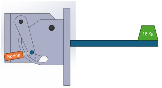
Current_setup_tosqzf.png
moment_1_hiic07.png

Force on spring: 18 x 9.81 x (0.170/0.040) = 750 N's

Potential Setup:
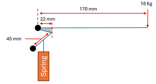
moment_2_yeal4g.png

Force on spring: 18 x 9.81 x (0.17-0.022) = 26 N's
 
Replies continue below

Recommended for you

Looks like a very inefficient mechanism. Not obvious how it is supposed to work.
Just by eyeball the spring forces seem way too low.
You need to account for the roller in the slot; the force can only be tangent to the slot edge.
 
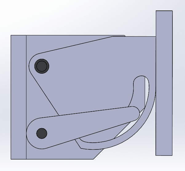
The Slot/CAM profile is needed to balance the spring compression at different angles - giving more or less force as required to give a counter balancing effect no matter the angle. Where do you see the issues here? please be specific. Also do you see anything wrong with the maths? See below CAD of the potential new setup. Any of these mechanism can work using a a torque spring instead of a compression spring
Potential_Setup_rn5a9m.png
 
An energy balance is the easiest approach.

Movement from one angle to the next results in the weight changing height by some amount and with it the potential energy - m*g*delta-h. This is the amount of effort the spring needs to supply (or absorb) via 1/2 k((x[sub]new[/sub]^2)-(x[sub]old[/sub]^2))

Since you can alter the spring constant, the amount of pre-tension, the location/leverage of the spring, and the cam the spring works against, there isn't just one formula.

I'd be on a spreadsheet that I can put in variations for all of this and create a graph of the energy stored in the spring vs the potential energy in the weight.
 
"Where do you see the issues here?"

Issue 1: You have not defined the problem.

"...do you see anything wrong with the maths?"

Your arithmetic is fine. Unfortunately the equations are not the ones that you need to solve. See issue 1.
 
Ah ok I can see I did a bad job of explaining my issue. The CAM and Spring in this design are easily designed to give a counterbalance effect. What I' more concerned about is calculating the correct force is on the spring if we just look at static horizontal position. So I was looking to find out if there is a lever action from the first moment because the spring is behind the pivot point and therefore the is a lever effect on the spring creating a 45mm/170mm ratio which amphiphiles the force on the spring by approx 4X. In moment 2 the spring is directly connected to the arm in front of the pivot point so there is no lever action, just a weight at a 148mm distance from the spring. The force for this moment is drastically lower based on my calc's, 26 N's as opposed to 750 N's. My questions is, are these assumptions correct when I'm just considering potential force on a spring from the weigh in a horizontal position? Thanks
 
" My questions is, are these assumptions correct when I'm just considering potential force on a spring from the weigh in a horizontal position? "

No, they are not.

Further, "just considering potential force on a spring from the weigh in a horizontal position" is an incomplete solution to the larger problem of "counter balancing effect no matter the angle."

See Issue 1.
 
Please ignore "counterbalancing effect no matter the angle". I am looking to find what force is needed by the spring to keep these two weights horizontal to the pivot point. Thank you

Pivot_bbd6o7.png
 
given those sketches, if you set sum(moments) = 0, for
case #1, the spring force =~ 18 * (170 / 40)
case #2, the spring force is =~ 18 * (170 / 22)
 
Case 1: About 750 N.

Case 2: About 1360 N.

Not enough information to be more precise.
 
Status
Not open for further replies.

Part and Inventory Search

Sponsor