One of the things that I've learned through my adventures here at Eng-Tips is that there really are parts of the world where the average structural designer skill level is both sorely lacking and utterly corrupted by an over-reliance on software. And the scariest part of it, in my opinion, is that it leaves many studious, conscientious, junior engineers without any access to quality mentoring. As I see it, there are only two realistic outcomes in the short term:
1) Those junior engineers get no quality mentoring and design terrible buildings. Who would stop them?
2) Those junior engineers get some mentoring from forums like this and design less terrible buildings.
The pragmatist in me is drawn to alternative #2. As such, I'll happily do my best to help out with some of the fundamentals here.
THE FALSE "RIGHTNESS" OF THE ELASTIC MOMENT DISTRIBUTION
As designers, we most often work with the results of linear elastic computer models built from prismatic elements. A moment distribution so obtained is predicated upon the following:
1) A material that behaves linearly elastically and;
2) Prismatic members.
In general neither of these things is strictly true with reinforced concrete. This is because reinforced members are generally cracked non-uniformly, reinforced non-uniformly, and subject to all manner of complex time dependent phenomena etc.
So why do we use the linearly elastic moment distribution? Here's a few reasons:
1) It's relatively easy to work out computationally. And we're lazy/efficient folk.
2) It's usually at least as valid as most any other moment distribution.
3) Because moments in the service range tend to be close to the linear elastic distributions, supplying reinforcing to match these distributions tends to minimize serviceability issues such as cracking.
4) Reinforced concrete is usually quite ductile but not infinitely so. Staying close to the linear elastic distribution tends to minimize the amount of ductility relied upon. Often codes will limit how far designers are allowed to deviate from linear elastic moment distributions. Deviations on the order of 15-30% are common depending on the jurisdiction.
The takeaway here is to recognize that the linear elastic moment distributions that our computers spit out at us are not gospel. Rather, they are but one of many possible moment distributions that can be used to successfully design continuous concrete members. We can use alternate moment distributions because modern reinforced concrete design is based on a model of
plasticity rather than strict elasticity. The practical motivation for redistributing moments is to reduce them in areas where rebar congestion has become a problem. Most often, this is at top steel locations over supports.
STATIC MOMENT CONCEPT
op said:
But I'm still googling about static moments so hope Kootk can shed more light on it as IDS also requested.
Yeah, my bad. Google doesn't seem to turn up squat and it's all buried in stuff pertaining to moment of inertial etc. I must be using non-conventional terminology or something. I find it unthinkable that such a fundamental concept could be getting so little web air play. I'll just go ahead and outline the method myself. I've included some sketches below as well.
In a very general sense, we can do this as designers:
1) Pretend that a continuous member is simply supported and calculate the moments accordingly.
2) Add any value of end moment to either end of the beam and, in doing so, reduce mid-span values.
3) Super impose the two triangular moment diagrams from #2 end moments with the #1 moments and reinforce for that.
Naturally, this process is limited by the stuff that I described above: presence of adjacent continuous framing and practical/code limits on redistribution based on ductility. As a simplification of the method described above, the classic static moment method goes like this:
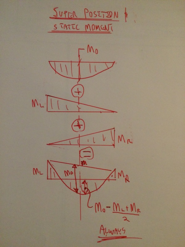
1) Assume simple support and calculate the moment diagram and mid-span moment Mo (the static moment).
2) Add in negative end moments as desired and reduce the mid-span moments accordingly.
3) To ensure satisfaction of equilibrium, ensure that (M_left + M_right)/2 + M_midspan = Mo. This can be done graphically by constructing the final moment diagram, connecting the end moments with a straight line, and ensuring that the vertical distance from the mid-span moment value to the line is still equal to the static moment (Mo).
I think that this is an important concept for you because your intuition seems to be telling you that moment can not just be assigned randomly. There needs to be some kind of "conservation of moment" like there is "conservation of energy" in thermodynamic systems. And you're right. The static moment (Mo) is the thing that must be maintained no matter what. It's your flexural design North Star so to speak. Many concrete codes still include a "Direct Design Method" for hand calculation. It usually starts with working out the static moment and then redistributing that moment along the span and, in the case of two way slabs, perpendicularly to the span. This ensures the satisfaction of equilibrium.
The takeaway here is to recognize that the normal process of design is to decide upon the moment field to be used and then to
supply reinforcement accordingly. It is rarely the case that we select reinforcement and then attempt to work out a suitable moment distribution to suit that reinforcement. The main exception, as I mentioned previously, is when we're trying to shed some moment at a location where rebar congestion has become a problem. And even then, the process usually goes:
1) Decide upon moment.
2) Reinforce for moment.
3) Tweak moment a bit to reduce congestion.
RELATIONSHIP BETWEEN REINFORCING AND MOMENTS
op said:
If a beam or column has certain moments and after you put rebars.. what would happen to the moments? For instance. A beam has certain moment at midpan, when you put the rebar to address the tension (bottom bars).. what would happen to the moments? I assume the beam would no longer deflect for the moments? But there should still be moment.. how much would be the retained moments or actual bending of the beam if there is sufficient tension bars?
OP said:
A more senior structural engineer told me when you put rebars in the beam, you straighten the beam and the moment/bending get less.. so I'm trying to find basis in his argument. But for beam with tension bars, the deflection is less. Isn't the moment same as deflection?
This concept is simply incorrect. Even though both are forms of strain, it is better to think in terms of
curvature rather than deflection because the relation of interest is this:
M = k * EI (M = moment; k = curvature; EI = stiffness).
So, if you could somehow reduce the curvature
without increasing EI then, yes, moment would be decreased by decreasing curvature (say.. 20%). However, how did you go about reducing deflection and curvature 20%? Probably by increasing EI 20%. So, when all is said and done, you've
decreased curvature 20%,
increased EI 20%, and changed the moment
not at all. This is the case, at least, when all members of a continuous system have their EI values increased proportionally. If some members are stiffened while other are not, then moment will migrate to the stiffened members.
OP said:
Let's take the example of a simple beam supported by two columns on the left and right. He stated that by putting more bars in the negative moments at support.. he can straighten the beam and control the moments at midspan and using less tension bars at midspan.
So long as a moment connection is detailed between the beam and column, this is true. The static moment requirement remains however. And it must be recognized that this is not merely a reduction of mid-span moment but a transfer of moment demand from the midspan to the ends of the beam. Moment is conserved as discussed above.
YOUR COLLEAGUES ODD BEAM DETAILS
op said:
I told him why the bars at midspan are not at bottom and mid height and he replied "the area covered by actual moment reaches into the mid height of the beam section at midspan so it's ok the rebars reaches up at mid height".
Your colleague may in fact be right. We'd need to review the framing plan in order to know for sure. Some reasons to reinforce the beam as detailed include:
1) If it's a beam more or less simple spanning between two supports, the top steel may just be nominal reinforcing for crack control.
2) In a 250 mm wide beam, having multiple layers of reinforcing with interior bar can cause issues with achieving proper concrete placement and consolidation.
3) So long as the vertical position of all reinforcing bars has been properly accounted for analytically, all bars below the neutral axis can indeed contribute to resisting flexural tension. While this may not be
optimal flexurally, it is valid.
4) In seismic design, sometimes this arrangement is used intentionally, to advantage. Let's leave that discussion for another day however.
I like to debate structural engineering theory -- a lot. If I challenge you on something, know that I'm doing so because I respect your opinion enough to either change it or adopt it.
![URL]](https://res.cloudinary.com/engtips/image/fetch/w_800,c_lfill,q_auto,f_auto,g_faces:center/[URL unfurl="true"]http://imageshack.com/a/img922/1369/IXDOSE.jpg[/URL])