Eng-Tips is the largest engineering community on the Internet

Intelligent Work Forums for Engineering Professionals

  • Congratulations waross on being selected by the Tek-Tips community for having the most helpful posts in the forums last week. Way to Go!

More Mating Issues 2

Status
Not open for further replies.

JSMachine

Mechanical
Oct 24, 2011
31
0
0
US
I have gotten pretty good with Solidworks over the past couple of days, especially since I figured out how to make parts mate. I had posted a thread earlier in the week requesting help with that.

Now, I have built a machine and it has probably a dozen or more parts. I have had pretty good luck so far with the mating process, but there are still a couple of areas I can't seem to grasp.

Here is one scenario:

I seem to do okay with mates as long as I have a reference point. For example, if I want to put a part directly down in the middle of a table, it easily mates when I select the bottom of the part and the top of the table. But, how do I put it in a certain place on that table (like the X and Y)? The only way I have figured out how to do this is to go back to the part file itself, create a sketch on the solid surface (for instance the table's top), and create what I call a footprint. I can usually put that footprint where I need it to be because I can dimension off of the edges of the table edges and get it there. Then, I go back to the part in the assembly, and when I mate the part, I simply grab one of the bottom edges of that part and line it up with one of the edges of the footprint. Then I do the other axis, whether it be X or Y. This lines the part up on the footprint and puts it where I need it to be.

I know there must be a correct way to do this. Am I doing it correctly or am I not?

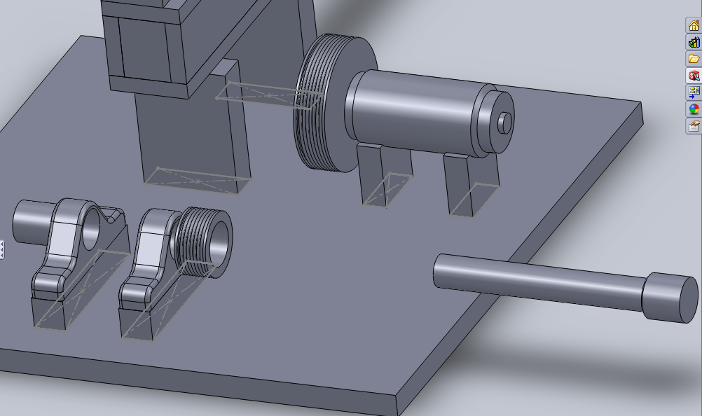
Here is an example of what I am talking about. In this picture I have attached, you can see the parts there. The long part in the horizontal plane is called an idler arm. The part I am trying to mate (enclosed in the orange square wireframe) is the idler wheel mount. I have mated the back side of the mount to the idler arm. I have lined up the top edge of the mount to the top edge of the idler arm. No I am trying to move the mount to the right (maybe the X axis? - but if you look close at the axis thing at the bottom left of the picture it looks more like the Z axis) towards that light gray line. That light gray line is a sketch that I went back and added to the idler arm part as a reference point just for the operation I am trying to perform. It serves no other purpose.

mateissue.jpg


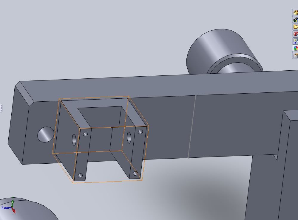
When I try to mate this, I cannot select the light gray line like I was able to do on the base (which is the original part in the assembly and fixed). This is why I don't think this is the correct way to do this. The mount is not fixed, it is set at float.

Thanks!
 
Replies continue below

Recommended for you

There are many ways to accomplish what you are attempting. The simplest would be a distance mate. You should be able to mate to sketch entities like you are trying to do. I do not know why it is not working in this instance. You could also create reference geometry (planes / axes) in the part and mate to that.

There is no best method. The distance mate will probably be the quickest to begin with. The other methods can make it easier to manipulate the design and make the model more robust to changes.

Eric
 
JSMachine,

Since you are relatively new to SWX and are learning on your own I highly recommend you work through all of the SWX tutorials (Help -> SolidWorks Tutorials). If you do them in order you will be quite pleased with what you learn and how easy SWX is to use. Your modeling will improve and so will assemblies and drawings. Your questions above would not be necessary and you certainly would not have to do the changes to the part as you speculate. Rather than feed you a fish, I recommend you learn to fish.

Good fishing!

- - -Updraft
 
I agree with Updraft ... work through all the tutorials
first.

I also agree with EEnd ... use a Distance mate.

But to answer your question, there is an option which may be preventing you from mating to the sketch.
Go to Tools > Options > System Options > External References and select Allow multiple contexts for parts when editing in assembly
 
The external referances options tab thing did the trick for the part in my question above. I have opened up the tutorials and started. I am first going through the mates section, but I will eventually do them all.

Thanks for the help folks.
 
Thank you ArtL. I see now what the distance mate does and how it works.

I can't seem to find anything in tutorials about the other issue I have. For some reason, I get an over-defining error message at times when I try to mate two parts.

In this picture below, you can see the shaft over to the right. It already has a concentric mate with the bores of the bearing pillow blocks to the left. When I try to bring the shaft up through the pillow blocks and place it into position, it gives me the error. The error message says "The default mate type (coincident) would over-define the assembly. Please select the mate type below"..Then if I click on "conicident" I get a message that says "The components cannot be moved to a position which satisfies this mate. Planar faces are not conicident. The seperation distance is (whatever it is)."

mateissue2.jpg


Also to the left of the left most bearing pillow block, you can see the actual bearing (part) which slides into the pillow block housing. I cannot get it to move into the housing either; it gives me the same error as above. It has the concentric mate, but I can't get it into the housing.
 
Ahh yes - the joys of mating: in SolidWorks that is. Sometime SW messes up and says something cannot be moved to a position, when it actually can, but most often the software is right. Remember, SW calculates at at least 8 decimal places. If you measure something, and the angle returned is 90.0°, then it can be tempting to think that means a right angle. Dig a little deeper by turning up the number of displayed digits on your measure tool, and you may see 90.00000012°. This will flat out prevent you from forming a potential mate with other constraints in place if you are trying to mate to something ACTUALLY @ 90°. Also a shaft in a bore with clearance can not be mated coincident, and concentric simataneously. In general, read up on Best Practices for mates. Construct your parts with symmetry about planes, use axis & etc.
 
The link does not work.

"Planar faces are not conicident."
That means one or more faces are not what you think they are. Use the Measure tool and select various pairs of faces to find the problem.
 
gwubs -

"-This will flat out prevent you from forming a potential mate with other constraints in place if you are trying to mate to something ACTUALLY @ 90°. Also a shaft in a bore with clearance can not be mated coincident, and concentric simataneously. In general, read up on Best Practices for mates. Construct your parts with symmetry about planes, use axis & etc."

I have assumed that when I request a mate with two surfaces, it automatically moves the part to a perfect line up with that plane. I had no idea this could happen.

Also, I looked but I have not found anything yet on why I can't use a coincident and concentric mate simultaniously. That is odd. What is the reasoning behind this?

Thanks
 
We deal with a lot of imported solids created in other, arcane, systems. As such, surfaces that were orthogonal do not always get translated as orthogonal. Where we might mate something using three coincident mates on "orthogonal" surfaces we sometimes get an error. This relates directly to what gwubs stated regarding the precision. In this case we simply use the 3-2-1 mating principal similar to defining primary, secondary and tertiary datums in GD&T.

In other words, if SWX is telling you there is a mate conflict then there is a mate conflict. Your job then is to figure out what that conflict is and/or to find a way to achieve the mates necessary. In our case we'll follow the 3-2-1 approach and do a surface-surface coincident mate, plus a line-surface coincident mate, plus a vertex-surface coincident mate. This is guaranteed to work.

A helpful tip is to pay attention to the degrees of freedom (DOG) and basically count them down. There are six DOG and a single surface-surface coincident mate satisfies three of them. If you were to then mate two orthogonal surfaces this only satisfies two of the remaining DOG, BUT it has the potential to conflict with a DOG that has already been satisfied.

So, how many DOG are satisfied when you mate coincident two lines?

- - -Updraft
 
gwubs said:
Also a shaft in a bore with clearance can not be mated coincident, and concentric simataneously.

JSMachine said:
"Also, I looked but I have not found anything yet on why I can't use a coincident and concentric mate simultaniously. That is odd. What is the reasoning behind this?"

I think gwubs is saying the circular surface of the shaft cannot have a concentric and coincident mate with the circular surface of the hole. A coincident mate can also be made with the end of the shaft and the outer face of the bearing block ... providing it is truly perpendicular to the axis of the hole.
 
Here is another pic with some better views.

mateissue3.jpg


in View 1, you can see where I have selected the face of the bearing. The bearing was of course out in free space when I inserted it into the assembly. The first mate was a coincident mate to get it to the same plane as the face of the pillow block. This also rotated it 90 degrees, because it was facing up to begin with. The second mate was a concentric mate to get it to line up with the hole it is supposed to go into in the pillow block. In View 1, you can see where I have oriented the assembly where I can select the face of the bearing (which I have) and then select this side face of the pillow block, to pull the bearing into position. I get the error.

In views 3 and 4, you can see the drive shaft sitting out to the side. It too was in free space when inserted into the assembly and turned up 90 degrees. The first mate got it coincident with the side of the base and flipped 90 degrees so it is horizontal now, and the second mate which was concentric got it lined up with the holes of the other parts. Now, when I try to select the end of the shaft, and the end of the pillow block which now has the bearing sitting up against it, it gives me the error. It doesn't really matter which pillow block, or any of the things there; everything I select that would pull the shaft through gives me the error. You can also see the drive pulley there. It goes on the larger diameter end of the shaft.

"Updraft - In our case we'll follow the 3-2-1 approach and do a surface-surface coincident mate, plus a line-surface coincident mate, plus a vertex-surface coincident mate. This is guaranteed to work.A helpful tip is to pay attention to the degrees of freedom (DOG) and basically count them down. There are six DOG and a single surface-surface coincident mate satisfies three of them. If you were to then mate two orthogonal surfaces this only satisfies two of the remaining DOG, BUT it has the potential to conflict with a DOG that has already been satisfied."

I'm not sure I understand this. I thought that a coincident mate was a coincident mate..I didn't know I could specify a type of coincident mate. Also as far as DOG goes, Where do I look to see how many degrees are satisfied after each mate?

Thanks
 
For each of the parts involved, activate the Measure tool (set to maximum precision), then select the Temporary Axis and the mating surface, and see what is reported. At least one of the pairs of axis & faces will not be perpendicular.
 
To do this, I went to tools, measure. the box comes up. I found the menu to set custom units, and went up to 8 on the length decimals and 8 on the angular decimals.When i measure I get readings, but I'm not sure I'm getting the right thing. I see no measurement that shows me the perpendicularity or an angle that my two parts are.
 
I did have a box a minute ago that had a few lines drawn around inside what I was measuring. It had different colored lines depicting the different axes. There were also boxes with X, Y and Z values. Now I can't get them to come up.

I would do a screen shot, but I there is nothing to capture..
 
Status
Not open for further replies.
Back
Top