Continue to Site

Eng-Tips is the largest engineering community on the Internet

Intelligent Work Forums for Engineering Professionals

  • Congratulations GregLocock on being selected by the Eng-Tips community for having the most helpful posts in the forums last week. Way to Go!

Motor Drive - Current contoller with speed limiting

Status
Not open for further replies.

K-Sci

Electrical
Jan 20, 2022
3
My goal is to drive a BLDC motor that provides a propulsion power assist that supplements the push force effort required from a user attempting to move a cart. The input command comes from a force sensor in the handles used to push the cart. The control loop includes torque (current) control but with a limit on the cart's ultimate speed.
The control scheme that appears to be most common for two variable loops uses cascaded control architecture. As you can see from the diagram below, I can't figure out how to include the speed limiting function in a cascaded loop architecture. This diagram illustrates where I'm stuck.
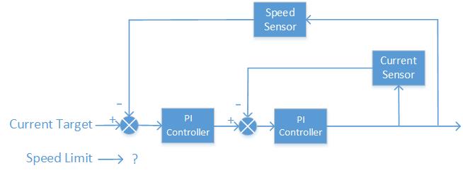
Control_Loop_2_urdz3w.jpg

It may help to know that I am trying to instruct my software engineer in how to write C coded firmware for a microchip MCU to perform this function. Any help that can be provided would be appreciated.
-Keith
 
Replies continue below

Recommended for you

You're current target must be the output of the outer loop's PI controller. The speed target goes into the difference function where you now show the current target. The speed target must be limited from 0 to max speed. The outer loop PI controller must have its output calibrated in units of current to give a proper current target signal to the inner loop difference function.

Also, you should show a few other things in the block diagram. The inner loop is missing the motor drive block, which will be between the inner loop PI controller and the current sensor tap. The outer loop is missing the cart block between the current sensor tap and the speed sensor tap, which includes the motor and the cart mechanical equipment.

xnuke
"Live and act within the limit of your knowledge and keep expanding it to the limit of your life." Ayn Rand, Atlas Shrugged.
Please see FAQ731-376 for tips on how to make the best use of Eng-Tips.
 
Do you need PID control of speed? I think you are just looking for a limit on speed.
 
You do not need to control current. You need to control the force applied to the force sensor. If the force exceeds the set point, the motor speeds up (up to the speed limit). When the force is below set point, the motor slows down.
 
Xnuke From what you said I think I had the inner and outer loops reversed and that the Current control loop should have been the outer loop. I incorporated the current limit as a PI signal that is only applied when the speed exceeds the limit. This is my best guess at this point. This is a complete guess. It still doesn't seem right.

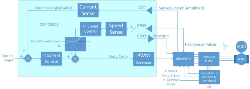
Control_Loop_2_th7jxh.jpg


BrianE22
> Do you need PID control of speed? I think you are just looking for a limit on speed.
You are exactly right. Only speed limiting is needed. The PID controller I proposed is more a product of my starting point than believing PID processing of the speed error signal is needed.

Compositepro
> You do not need to control current. You need to control the force applied to the force sensor. If the force exceeds the set point, the motor speeds up (up to the speed limit). When the force is below set point, the motor slows down

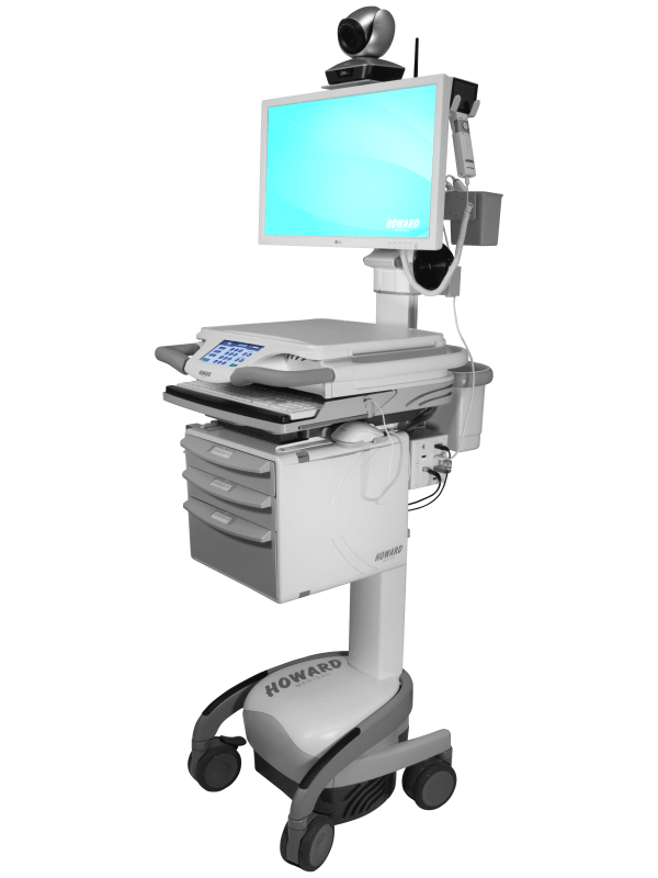
The system input is the sum of forces from two force sensors one in the right handle and one in the left handles. Here's a photo of the cart showing the handles on the left.
telecare_telemedicine_cart_2_zkmgem.png

-Keith
 
I'd recommend to check if you need to fulfill functional safety requirements (design the circuit and software in a way that failures don't harm anyone). If you do not consider such a requirement from the very beginning later modification will be cumbersome.
 
Status
Not open for further replies.

Part and Inventory Search

Sponsor