Continue to Site

Eng-Tips is the largest engineering community on the Internet

Intelligent Work Forums for Engineering Professionals

  • Congratulations IDS on being selected by the Eng-Tips community for having the most helpful posts in the forums last week. Way to Go!

motor nameplate question - R1/RX/X1/X2/XM? 6

Status
Not open for further replies.

dirtyc7

Electrical
Dec 13, 2016
2
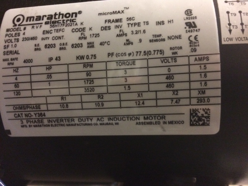
Please see the inserted image of a small 3-phase motor name plate:
IMG_2752_yn3xfk.jpg


I do not understand what the R1, R2, X1, X2, XM terms mean. It seems like the R1, R2 are the number of ohms I should see if I measure from phase lead to phase lead (while disconnected from power source, of course).
However, why is there only 2 of them if there are 3 phases?
tt
My motor has 9 wire leads sticking out of it. When I measured them all (T1 to 2, 3,...9. T2 to 1, 3,...9 etc) I found that T1-T4, T2-T5, T3-T6 all measured 4.8 ohm each. Any combination of T7,8,9 measured 8.9 ohm.

Outside of those measurements, all other leads to each other were in the megaohms

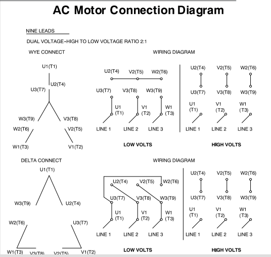
The measurements between motor leads suggests, per the chart below, that my motor coils are a wye-style load.
But, even if that is true, why I don't I get the 10.8 ohms on the name plate? if there are 3 phases, why is there only R1, R2? What even ARE X1, X2, Xm?
low-high-voltage-wiring_pzcqb6.png
 
Replies continue below

Recommended for you

Generally, R1 and X1 are resistance and reactance per phase of stator ; R2 and X2 of rotor; XM is magnetizing reactance.
Note that you should make a Ohm-measurements at high voltage connection ( join 4-7; 5-8; 6-9), but I don't know whether or not the internal Wye is accessible. If not, try to measure the ohms between two phases and divide by 2.

[URL unfurl="true"]http://winding.wixsite.com/design[/url]
 
That is a 230/460 Volt motor. On the 460 Volt connection two windings will be in series for 9.6 Ohms cold.
10.8 Ohms seems reasonable when the motor is at operating temperature.
There is enough of the connection diagram visible in the photo to identify this as a wye connected motor so don't worry about the delta connection diagram. (And certainly don't try to use the delta diagram.)
Bill
--------------------
"Why not the best?"
Jimmy Carter
 
dirtyc7; Notice that the motor is labeled "Inverter Duty". The R, X, and XM values are what vector based inverters need to know so they can actually control the motor. Most modern drives can interrogate the motor during a setup test but some can not and so, part of the 'inverter duty', is to provide those values for manual entry into a drive. I don't believe you should be able to actually measure any of them walking up to the motor with a meter in hand.

Keith Cress
kcress -
 
Keith is right. That is data for "Vector Nerds" that insist on manually entering motor data into Vector Drives rather than allow the drive to "auto-tune" itself to the motor. The only reasons people use that data are:

1) the motor is permanently connected to a load and the load cannot be run in a rotating auto-tune routine, but they want better performance than you will get with a "static" non-rotating auto-tune, or

2) they want to "hack" the motor performance in some way that the auto-tune would not allow in order to use it for some special application, knowing the likely effects of that hacking.


"You measure the size of the accomplishment by the obstacles you had to overcome to reach your goals" -- Booker T. Washington
 
All excellent points. R1/X1 are stator R2/X2 are rotor. Thanks for the replies gentlemen.
And yes, now that drives are so intelligent, I feel like younger engineers like myself have become ignorant to how things work because we can get them working without really understanding them. Not sure how I feel about that, but it is what it is. time is billable and its always on to the next project, understanding be damned.
 
Status
Not open for further replies.

Part and Inventory Search

Sponsor