Continue to Site

Eng-Tips is the largest engineering community on the Internet

Intelligent Work Forums for Engineering Professionals

  • Congratulations KootK on being selected by the Eng-Tips community for having the most helpful posts in the forums last week. Way to Go!

Motor Peak Torque during Startup 1

Status
Not open for further replies.

fsxn155

Mechanical
Jun 29, 2020
29
Dear All
We are facing problem of repeated Coupling Failures on a Centrifugal Compressor Train driven by a 2967 RPM, 2 pole, 3 phase, 50 Hz Squirrel Cage Induction Motor.
Attached is the Screenshot of Motor Curves showing Motor can develop up to 2.5 times full load torque during startup which is well above the Torque demand by the Load (Compressor Inertia & Process Gas Load) during startup.

Being from Mechanical background, I am unable to understand if Motor actually develops Peak Torque as shown in the Curve ?
As this Torque is well above Load demand, how this Torque impacts/effects Load ? it is utilized in accelerating the Compressor quickly to Rated RPM ?

Generally Speaking do these type of Motors develop Peak Starting Torque exceeding the Load Demand ? and if So Peak Torque exceeding the Load demand manifests in rapid ramp up/acceleration of Compressor to rated RPM ?
 
 https://files.engineering.com/getfile.aspx?folder=c916b2a2-8742-4fcf-a884-bf2afe62facc&file=Motor_Curves.png
Replies continue below

Recommended for you

During acceleration, the motor torque is driving against the rotational inertia of the rotating elements in your compressor. Your coupling needs to be able to resist this force. Are you using the OEM specified coupling, or an after market coupling?
Have you verified alignment? For this application, use laser alignment tools if available.
 
Dear Mr. fsxn155 (Mechanical)(OP)9 Feb 22 19:42
"... We are facing problem of repeated Coupling Failures on a Centrifugal Compressor Train driven by a .... Squirrel Cage Induction Motor...Attached is the Screenshot of Motor Curves showing Motor can develop #1) up to 2.5 times full load torque during startup which is well above the Torque demand by the Load ... during startup... I am unable to understand #2)if Motor actually develops Peak Torque as shown in the Curve ?..."
1. The motor curve is in order. It is typical to most motors.
2. Regarding question #1, 2.5 ST/FLT is >0.9 speed ; NOT at starting. At starting with full voltage is approx 0.6 . This is normal.
3. Regarding #2, Yes, it is normal. See 2. above.
4. Suggestion: check the alignment, foundation/vibration and quality of the coupling.
5. Opinion: most likely it is a "mechanical" problem rather than an "electrical".
Che Kuan Yau (Singapore)


  0.9 speed
fsxn:
Are you failing the coupling DURING the acceleration? Or only after some time spent running at speed? If it's during acceleration, then the torque rating of the coupling (or bolts, if the halves are bolted together) is suspect - along with things like interference fits between coupling hub and motor shaft, keys being undersized to either shaft or coupling keyway, misalignment between coupling halves, etc. If it's during some time spent running, you can pretty much rule out the peak torque issue - which puts the root cause squarely back in the mechanical camp.

You should also be aware that even a centrifugal compressor does not provide a "flat" load, even when started unloaded. There will be torque fluctuations associated with the design of the compressive elements (piston throw, angle, balance, etc.) that can also introduce torsional instability leading to premature mechanical failures.

Is there torsional data for the drive train as a whole? For most applications, having the driver (motor) inertia larger than the driven (compressor) seems to dampen the worst of the torsional effects. Given that you're using a squirrel cage induction motor as the driver, I suspect that may not be the case. A close look at how the system behaves under different torsional excitations might be eye-opening.

Converting energy to motion for more than half a century
 
I think you're asking whether the coupling ever sees that peak torque shown on the torque speed curve. I'll say "no", under a simplified model, with some caveats when we talk about the assumptions at the end.

Let's make three assumptions:

[ul]
[li]1. Let's assume there is no torque drawn by the load. We just have to accelerate the rotating inertia of the motor JM and the load JL.[/li]
[li]2. Let's use the simple model of the motor described by it's torque speed curve (no torque oscillations introduced by the motor electrical oscillations[/li]
[li]3. We're going to everything is perfectly rigid (no oscillations introduces by rotary mass spring system).[/li]
[/ul]

Let Te(w) represent motor electrical torque as a function of speed and TC represent torque transmitted through the coupling.

Start with the rotational equivalent of Newton's 2nd law f=m*a... T = J*w':
Apply it first to the whole system (eq1) and then to the load (eq2):
w' = Te(w) / (JL + JM) (eq1)
TC = w' JL (eq2)
Combine eq1 and eq2:
TC = {Te(w) / (JL + JM)]} * JL
TC = Te(w) * [JL / (JL + JM)]

For electrical folks, it resembles a voltage divider.
The quantity in square brackets is less than 1, so TC < Te < Peak torque shown on the curve under these assumptions
(Sanity checks: if JL = 0, TC = 0; IF JL>>JM, TC~ TE)

But it was a simplified model, so let's revisit those three assumptions:

[ul]
[li]1. You could add the load torque back in without too much trouble. Just change the LHS of eq1 to Te(w) - TL(w), add TL to the RHS of equation 2, and use the two equations to solve for the two unknowns TC and w' (we don't actually need w', we just want to eliminate it from our expression for TC).[/li]
[li]2. In the real world the electrical transient can cause oscillatory torque characteristics of the starting motor which are not captured in the torque speed curve (the torque speed curve represents a quasistatic approximation to the full transient model of an induction motor). And that holds even for perfectly rigid rotor components that do not introduce mechanical mass-spring oscillations.[/li]
[li]3. In the real world there may also be oscillatory components introduced by torsional oscillations of the non-rigid mechanical mass spring system.[/li]
[/ul]
If you did the algebra work to remove assumption 1 as discussed above, you'd find it would not change the conclusion TC<Te, since some of the electrical torque still has to go towards accelerating JM and therefore that w'*JM component of torque never reaches the coupling. For assumptions 2 and 3, it's more complicated and you can't be sure without more detailed analysis or measurements.
 
What you're saying Pete is that the accel torque is used to accelerate both the motor rotor and the load so some of the accel torque doesn't make it to the coupler, right?
 
the accel torque is used to accelerate both the motor rotor and the load so some of the accel torque doesn't make it to the coupler, right?
Yup Lionel, that's it (much simpler!)

(I did add that into my last paragraph in one of my later edits)

=====================================
(2B)+(2B)' ?
 
Starting a direct connected fan with DOL/ATL motor start will of course add the complication of fan loading rising as the motor accelerates, substantially altering the speed torque curve.

CR

"As iron sharpens iron, so one person sharpens another." [Proverbs 27:17, NIV]
 
electricpete said:
1. You could add the load torque back in without too much trouble. Just change the LHS of eq1 to Te(w) - TL(w), add TL to the RHS of equation 2, and use the two equations to solve for the two unknowns TC and w' (we don't actually need w', we just want to eliminate it from our expression for TC).
oh what the heck. I don't want to do my real work anyway. Here is the same analysis without assumption 1. So TL(w) gets subtracted from LHS of eq1 and added to RHS of eq2:

Apply it first to the whole system (eq1) and then to the load (eq2):
w' = [Te(w)-TL(w)] / [JL + JM] (eq1)
TC = w' JL (eq2) + TL(w) (eq2)
Combine eq1 and eq2:
TC = {[Te(w)-TL(w)] / [JL + JM)]}* JL + TL(w)
TC = {[Te(w)-TL(w)] * [JL / (JL + JM)]} + TL(w)
TC = Te(w) * [JL / (JL + JM)] + TL(w) -TL(w) * [JL / (JL + JM)]
TC = Te(w) * [JL / (JL + JM)] + TL(w)*{1- [JL / (JL + JM)]}
TC = Te(w) * [JL / (JL + JM)] + TL(w)*[JM / (JL + JM) ]

Now that's an interesting result.

The first term looks just like it did before. But we add a second term to it. So the max coupling torque will be higher when you add load torque into the model than when you are just trying to accelerate the inertias, as I think crshears was trying to point out.

Look at that second term. It looks very similar to the first term, but in an end-for-end symmetric kind of way. If we ignore the fact that Te and TL are functions of w, then we could view it as a linear time invariant system, and then maybe we should not be surprised that the torque stress at the coupling resembles a superposition of the stress from torque applied only at one end and the stress from torque applied only at the other end.

We can also deduce from the algebraic form of the equation that TC is still less than Te during acceleration. i.e. we can note that Tc would be exactly equal to Te(w) IF TL(w) was also equal to TE(w), but since TL is always less than Te(w) during acceleration (otherwise we stall), then TC will also be less than Te(w) during acceleration (or we could just uses Lionel's logic again to get there a lot quicker). And by the way, at the end of acceleration when we reach steady state where TL(w)=TE(w), then at that time we have the expected result that TC=Te in steady state. Sanity check passes (I think I'm still sane!)

=====================================
(2B)+(2B)' ?
 
. . . as I think crshears was trying to point out.

Correct; that is what I was trying, in my own intuitive rather than mathematical way, to do.

CR

"As iron sharpens iron, so one person sharpens another." [Proverbs 27:17, NIV]
 
electricpete's approach is more correct in detail then mine. I would probably leave out the effect of motor inertia in my calculations, as it results in a more conservative design.
My bet is that your coupling alignment is off.
[URL unfurl="true" said:
https://www.shaftalignment.hamarlaser.com/benefits-of-laser-shaft-alignment/?r=1[/URL]]
Screenshot_from_2022-02-10_19-48-40_pxtaib.png
 
Dear All
Many thanks for the extremely useful info from all of you. Special Thanks to electricpete for the detailed explanation

Dear crshears
Please note that in the attached Curves, the lowest curve is Load Curve which increases exponentially with Speed throughout acceleration phase. (Torque Requirement due to gas flow within Centrifugal Compressor increases as with square of RPM). So I assume the Torque Speed Curve has accounted for Compressor/Load Torque increase during acceleration

So from the above discussion above I can infer that Maximum Coupling Torque during startup is the Peak Torque shown on Motor Torque Speed Curve minus Torque consumed in accelerating Motor Rotor ?
 
fsxn155 said:
So from the above discussion above I can infer that Maximum Coupling Torque during startup is the Peak Torque shown on Motor Torque Speed Curve minus Torque consumed in accelerating Motor Rotor ?
Yes.
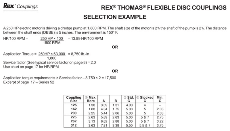
Coupling manufacturers recommend a rather cruder approach to sizing using service factors
see page 8 of this reference for an example [URL unfurl="true" said:
https://pdf.directindustry.com/pdf/rexnord-industries-llc/thomas-coupling-catalog/7386-330607-_2.html[/URL]]
Screenshot_from_2022-02-11_05-23-45_o1g2tt.png
 
Status
Not open for further replies.

Part and Inventory Search

Sponsor