Continue to Site

Eng-Tips is the largest engineering community on the Internet

Intelligent Work Forums for Engineering Professionals

  • Congratulations KootK on being selected by the Eng-Tips community for having the most helpful posts in the forums last week. Way to Go!

motor spline failure

Status
Not open for further replies.

mxs

Electrical
Apr 26, 2018
2
We are building EV shuttle buses using a motor with splined output shaft and a spline coupling shaft to the gearbox. There have been a lot of failures of the motor and shaft spline since we switched to using a new gearbox a few years ago.

The old coupling shaft was broach cut whereas the new one is cut with a shaping tool. Because the old gearbox had 24 tooth spline the same as the motor, but the new one has a 23 tooth. There have not been any failure of the gearbox spline, but it's spline is also much longer than the motor side.

The coupling shaft is now sold to us by the motor vendor. In the past we had been using an overseas supplier with a really rough EDM cut, and then went to the gearbox vendor who was... quite literally... cutting the spline in the wrong area of the shaft. Since moving to the part supplied by motor vendor, the failures of the new part have been much lower but they are still occurring and we are not sure of the cause. I'm waiting to hear back on the hardness and material of the shafts. IIRC they are both hardened to around Rc 55.

I think there are two possibilities, either the female spline is being cut wrong in the input shaft, or the motor and gearbox input shafts are not in alignment.

If the shaft spline is cut wrong it would be possible to move to a two-piece shaft where each side is broach cut separately and then bolted together. The broach cut seems to fit better than the shaped cut shafts ever have, although the motor manufacturer says it is within tolerance.

The motor manufacturer recommended removing the locating pins from the bellhousing ("plate") to the gearbox so the coupling shaft itself is used to locate the two shafts together. The old gearbox had a built in locating device and no plate was necessary. (of course, it was a sh*t box with a ton of other issues internally).

We have seen these splines fail from 10,000 miles or sooner. Of course there are some that are over 100,000 without failure. It seems like there are some vehicles that have a much higher chance of failure. To me this would indicate that when the shaft is replaced the mechanic is not installing the motor correctly, creating (or failing to correct) an alignment problem between the two shafts.

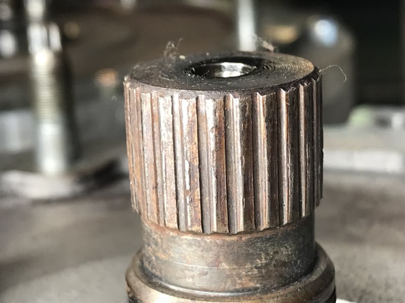
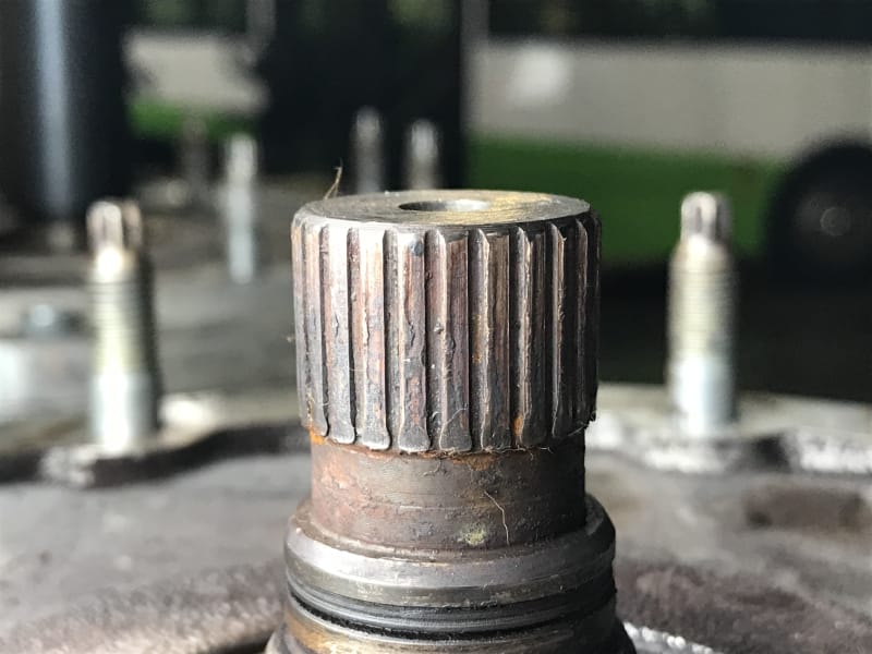
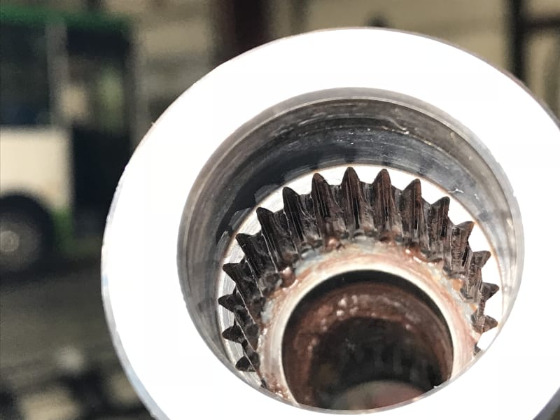
I'm attaching some photos of the failed parts, IDK if anybody can tell me from the photo what is causing the failure.
Thanks!
IMG_2680_iimjbw.jpg

IMG_2682_cuferu.jpg

IMG_2687_mkpwwt.jpg
 
Replies continue below

Recommended for you

Couple of quick takes:

1)Are these out in the environment, unprotected? There appears to be a lot of corrosion on these parts.

Corrosion on high strength steel parts like this is a killer. Pitting on the contact surfaces which see a LOT of stress will cause sporadic and unpredictable failures. Are these parts coated with grease when they are assembled?

2) To my eye both the male and female splines which have failed have a LOT of material left. Looking at your picture of the female coupling, the as-assembled profile of the splines is visible near the bottom, where the male splines didn't mate and the material didn't fail. The 'lip' of remaining material shows you how much overlap there was between the two sets of splines in operation.

That overlap, to me, looks very small. While these splines obviously fit together, it looks like they may not have the same pitch diameter.
 
I see what appears to be an o-ring on the shaft making it look like the coupler is supposed to seal over the shaft. So, why the corrosion?

Saying EV, it makes me wonder if you have the motor shifting between motoring and regen too much. If you don't get the control loops right it can transition back and forth rapidly and hammer on any parts with clearance such as couplers and gear sets.

 
Do you have a coworker asking this same question in another forum?

Or do you have two forum IDs?


If those other pictures are your same parts, the round wear pattern (of missing material from the male splines, post #2 of that thread) indicates you have a severe misalignment problem.
 
Perhaps I'm seeing it wrong in the first picture, but it looks like the worn splines are more worn leading toward the bottom of the teeth indicating misalignment.

Other than that, is the lubricant the same between the factory supplied parts any what you are using during maintenance?

Andrew H.
 
That is not us but we have asked an ME consultant for assistance with the issue. I am almost positive it is him. (Hi Steve!) The drawing and technical data is definitely our part, we have provided that data to consultant.

I can provide further assembly details but we were using previously a buna-n o ring which is not grease resistant. We are using Aeroshell #22 grease per the motor MFG's spec. We have seen the grease fly out and spray on the bellhousing which suggests the seal is inadequate. Now we are using a viton o-ring and I'm going to evaluate viton rings with an X cross section.

To correct the alignment issue, we were previously using undersized locating pins from the motor to the plate. This created an alignment problem. The gearbox was located to the plate using split pins which were tight and reinforced the misalignment. Now we are using split pins from the motor to the plate, and allowing the shaft to locate the gearbox as it is installed. This should help the alignment problem if not solve it completely. We're assuming that the coupling shaft is adequate to locate the motor to the gearbox; there is no play and this recommendation came to us from the motor manufacturer.
 
Have you done any analysis to determine exactly how straight all of these parts are, and how accurate the alignment is that you're getting as a result? There may be grist there worth grinding.

 
I question the spline tolerances and fits. With so much more wear on one of them this looks like a fit up issue.
With grease on them these should take some effort to slide together.

= = = = = = = = = = = = = = = = = = = =
P.E. Metallurgy, Plymouth Tube
 
Your spline dimensions do not appear to be a correct match.
 
If you can get the spline to seal properly there are better options for grease. Kop-Flex greases have polymer thickeners that don't separate out due to centrifugal forces. We were experiencing similar spline failures in a type of equipment we operate. We would prefer to run Kop-Flex but without a seal it leaves the coupling too quickly. Mobilgrease 28 has more viscosity and resists separating well enough to reduce the re-lubrication interval to annually.
 
I agree with the dimensional match along with other possible problems, such as hardness, torsional vibrations, proper sizing for the load etc. How about a picture with a scale (measurement).
 
We used to coat them with WS2 and leave them dry.
Reduced fretting damage.

= = = = = = = = = = = = = = = = = = = =
P.E. Metallurgy, Plymouth Tube
 
when it comes to splines, the most common modes of failure I see are as follows

1.) Dissimilar hardness, (typically the easier/less expensive to replace side is slightly less hard)
2.) Dissimilar designs, (Making sure the female and male are not only the right pitch but also similar angle/root/crown shape combo. i.e 30 deg flat side fillet root)
3.) Improper fit, What is the application, do you need a major diameter fit?
4.) Trying to get splines to take up misalignment, they are great self centering tools, but they are not gear couplings.
5.) Poor manufacturing/design techniques, facilitating bad contact points. (Usually from when someone is manufacturing off of a drawn spline in 3D CAD)

When it comes to couplings we are always here to help.
 
Ed, is this WS2 coating a paste or is it something that is chemically/mechanically bonded to the spline and requires parts be sent to a specialist for application?
 
We sent them out and the tungsten di-sulfide was applied by PVD I think.

= = = = = = = = = = = = = = = = = = = =
P.E. Metallurgy, Plymouth Tube
 
Hi, I work with the OP and have been involved in this project. In reviewing all the data we have collected I am left with the question of just how much tolerance there is in the alignment of the two shafts? We sent a prototype (that has performed well in the field) and two production adapter plates to a metrology lab to be compared. The adapter plate is what holds the motor, coupler and gearbox in alignment. It doeesn't appear that the shaft alignment could be any more than .005 different due to this part.

Thoughts?
 
If the motor and gearbox housings are locked into place and the coupling between the motor and gearbox shafts is rigid allowing no flexibility ... 0.005" misalignment is horrendous.

Backlash (especially if there are torque reversals, which there will be in this application) and misalignment are both deadly.
 
The actual variance is probably less than that. Thee coupler is provided by the motor manufacturer and you can feel a slight amount of backlash - which they say is OK -. Their solution is to assemble the motor, adapter and coupler with the shaft facing up the place the gearbox onto the coupler, without alignment pins, allowing the coupler to align everything. We have also upgraded the o-ings to get a better seal and keep the grease in the coupler.
 
"Their solution is to assemble the motor, adapter and coupler with the shaft facing up the place the gearbox onto the coupler, without alignment pins, allowing the coupler to align everything"

This would not ensure the best shaft alignment, since it is only based on "feel" of loose parts and not on shaft alignment measurements.

Walt
 
Status
Not open for further replies.

Part and Inventory Search

Sponsor