We are building EV shuttle buses using a motor with splined output shaft and a spline coupling shaft to the gearbox. There have been a lot of failures of the motor and shaft spline since we switched to using a new gearbox a few years ago.
The old coupling shaft was broach cut whereas the new one is cut with a shaping tool. Because the old gearbox had 24 tooth spline the same as the motor, but the new one has a 23 tooth. There have not been any failure of the gearbox spline, but it's spline is also much longer than the motor side.
The coupling shaft is now sold to us by the motor vendor. In the past we had been using an overseas supplier with a really rough EDM cut, and then went to the gearbox vendor who was... quite literally... cutting the spline in the wrong area of the shaft. Since moving to the part supplied by motor vendor, the failures of the new part have been much lower but they are still occurring and we are not sure of the cause. I'm waiting to hear back on the hardness and material of the shafts. IIRC they are both hardened to around Rc 55.
I think there are two possibilities, either the female spline is being cut wrong in the input shaft, or the motor and gearbox input shafts are not in alignment.
If the shaft spline is cut wrong it would be possible to move to a two-piece shaft where each side is broach cut separately and then bolted together. The broach cut seems to fit better than the shaped cut shafts ever have, although the motor manufacturer says it is within tolerance.
The motor manufacturer recommended removing the locating pins from the bellhousing ("plate") to the gearbox so the coupling shaft itself is used to locate the two shafts together. The old gearbox had a built in locating device and no plate was necessary. (of course, it was a sh*t box with a ton of other issues internally).
We have seen these splines fail from 10,000 miles or sooner. Of course there are some that are over 100,000 without failure. It seems like there are some vehicles that have a much higher chance of failure. To me this would indicate that when the shaft is replaced the mechanic is not installing the motor correctly, creating (or failing to correct) an alignment problem between the two shafts.
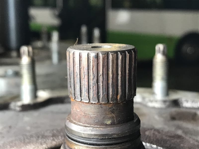
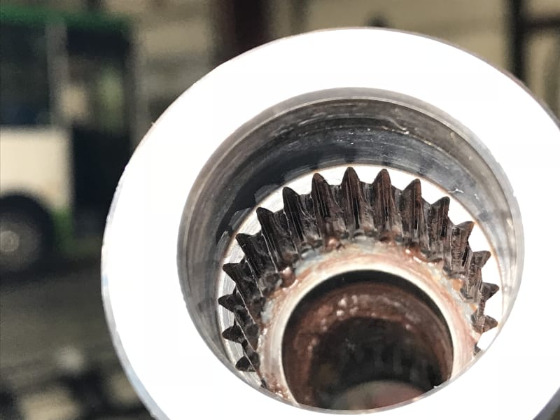
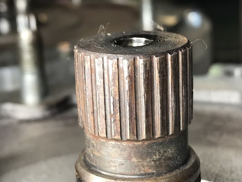
I'm attaching some photos of the failed parts, IDK if anybody can tell me from the photo what is causing the failure.
Thanks!
The old coupling shaft was broach cut whereas the new one is cut with a shaping tool. Because the old gearbox had 24 tooth spline the same as the motor, but the new one has a 23 tooth. There have not been any failure of the gearbox spline, but it's spline is also much longer than the motor side.
The coupling shaft is now sold to us by the motor vendor. In the past we had been using an overseas supplier with a really rough EDM cut, and then went to the gearbox vendor who was... quite literally... cutting the spline in the wrong area of the shaft. Since moving to the part supplied by motor vendor, the failures of the new part have been much lower but they are still occurring and we are not sure of the cause. I'm waiting to hear back on the hardness and material of the shafts. IIRC they are both hardened to around Rc 55.
I think there are two possibilities, either the female spline is being cut wrong in the input shaft, or the motor and gearbox input shafts are not in alignment.
If the shaft spline is cut wrong it would be possible to move to a two-piece shaft where each side is broach cut separately and then bolted together. The broach cut seems to fit better than the shaped cut shafts ever have, although the motor manufacturer says it is within tolerance.
The motor manufacturer recommended removing the locating pins from the bellhousing ("plate") to the gearbox so the coupling shaft itself is used to locate the two shafts together. The old gearbox had a built in locating device and no plate was necessary. (of course, it was a sh*t box with a ton of other issues internally).
We have seen these splines fail from 10,000 miles or sooner. Of course there are some that are over 100,000 without failure. It seems like there are some vehicles that have a much higher chance of failure. To me this would indicate that when the shaft is replaced the mechanic is not installing the motor correctly, creating (or failing to correct) an alignment problem between the two shafts.
I'm attaching some photos of the failed parts, IDK if anybody can tell me from the photo what is causing the failure.
Thanks!