Continue to Site

Eng-Tips is the largest engineering community on the Internet

Intelligent Work Forums for Engineering Professionals

  • Congratulations IDS on being selected by the Eng-Tips community for having the most helpful posts in the forums last week. Way to Go!

Motor Starting Study Important Parameters

Status
Not open for further replies.

triden55

Electrical
May 17, 2012
12
I was recently asked to do a motor starting study by the local utility for a 250hp vertical turbine pump. They are worried that the line voltage may sag more than 2% on startup, and if so, they may place restriction on time of day that it can be run. Now, I know enough in ETAP to be dangerous, and I was able to complete the majority of the study, but I don't have the confidence in my results that I would like.

The motor is connected to a Siemens voltage ramp soft starter.

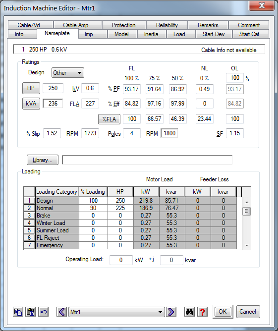
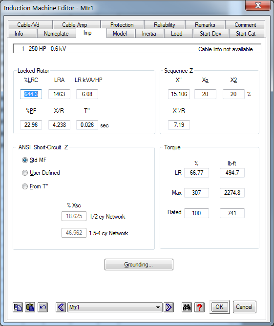
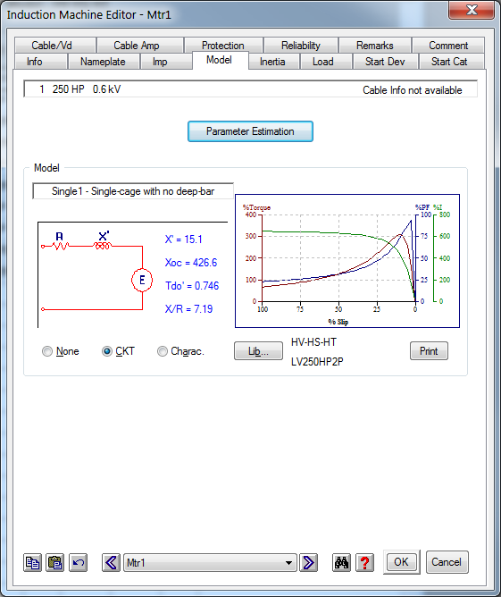
My main question is, what kind of motor parameters are precisely required, and what parameters can be estimated? The nametag on the motor doesn't give too much more information besides HP, FLA, Voltage. Is it important that my model is accurate for X', X/R, Tdo, etc?

Trying to learn as much as possible.

Thanks.
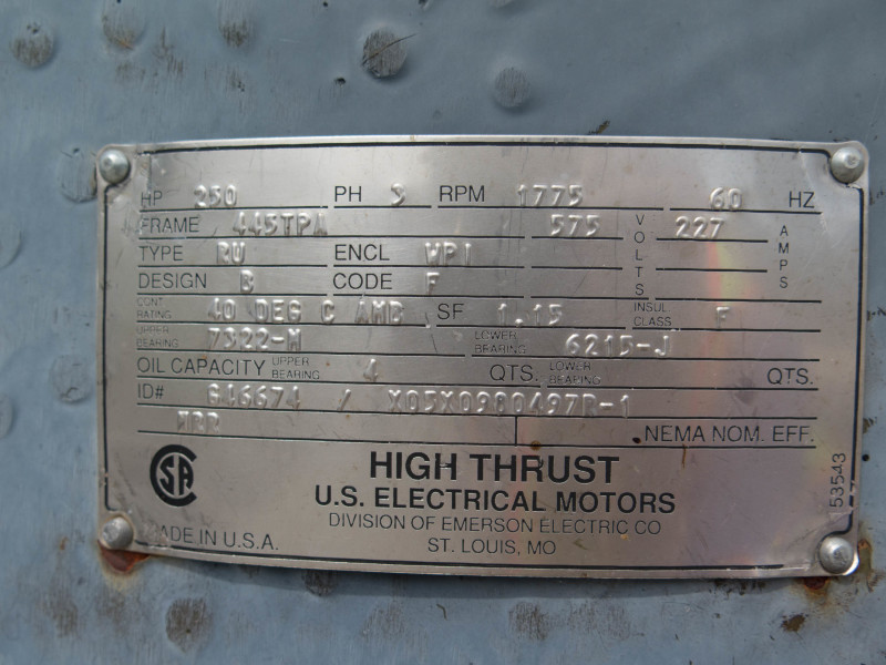
01101015-Field_Report-2015MAY12_19_of_87_r4guvm.jpg


1_btxnml.png


2_mkghda.png


3_bs5nwb.png
 
Replies continue below

Recommended for you

It is important to have the source impedance. It looks like all you show is the motor parameters.

From the source impedance and locked rotor amps, you should be able to calculate the voltage drop by hand without relying on ETAP. Then you can plug and play with ETAP and have some confidence in the results.
 
magoo2,

Luckily I do have the source impedances and have used those in the simulation. R1=4.71, X1=17.29, Symmetrical Fault Current = 800 amps. I am getting about 2.5% voltage drop at the source which means there will be restriction on when this motor can start. I'm just not confident in this results as I am simulating for a dynamic acceleration (pump load).
 
What units are the source impedance values in? Ohms?

With 600 V supply, your source impedance would be around 0.433 ohms to give you an 800 A fault current.

Am I misinterpreting what you provided?
 
Source voltage is 25kv, and goes through a 25k/600 WYE transformer with 6.3% Z then to motor starter. I gave you source impedance for the utility demarcation location which is where we need to check voltage drop. Impedances are in ohms, yes.
 
800 A / 2.5% x 2% = 640 Amps.
Set your soft starter to limit the current to 640 Amps.


Bill
--------------------
"Why not the best?"
Jimmy Carter
 
waross,

I wish I could, but this is a very simple soft starter. It's a Siemens SIKOSTART 3RW34 which only has a voltage limit and ramp time. There is no direct current limiting settings. I'm just looking for some confirmation that 2.5% drop on the 25kV line seems reasonable.
 
The information provided by OP are abstracts. 25 kV/600 V transformer kVA rating is also very important. As a first step simulate the motor starting by considering the DOL start. Check what is the voltage drop. Then apply the suitable multiplication factor (to correct it to the soft starter output voltage). This should give you a reasonable indication, on the gravity of the problem.

Normally, the soft starter vendor provides the exact calculation, which he performs during the design or tendering stage. You should use that value, which is generally trustworthy.
 
Both the motor and load models need to be correct if you want to properly simulate reduced voltage starting.
 
Just by the way, the 3RW34 is long obsolete and the factory that built them is closed and gone, no new parts have been made for it for years now. The first time it fails, you will have to replace it with something completely different anyway, but at that time, you will be shut down and losing even more money. Might be time to consider modernizing it now while you are installing the machine.


"You measure the size of the accomplishment by the obstacles you had to overcome to reach your goals" -- Booker T. Washington
 
2% drop seems unnecessarily restrictive for motor starting. I think the normal limit for across-the-line starting is 80% voltage at the motor.
 
jraef,

This I know. Little back story...

This 25kv service and 250hp pump was installed for the farmer about 20 years ago for crop irrigation. Well about 4 year ago, one of the overhead distribution poles rotted and snapped off which is typical for pine poles, hence the mandate to only use cedar around here now. The utility saw the overturned pole (still hanging by the conductors) because they were installing a new transmission line in the area, so they installed a new pole for the farmer for free. They left the fuses open on the service until everything was checked over by an engineer and electrician, which was completed with no real issues. So he calls the utility to reconnect the fuses and they have no record of the original service agreement which means we have to reapply and follow through like it's a brand new service. Because of this, the utility has now asked for a motor starting study as anything >50hp in the area requires due diligence to make sure starting and running conditions doesn't adversely affect the utility.

Back in '94, the pump originally did have a VFD installed, but it failed and an electrician installed the SIKOSTART which was a big mistake. With the VFD, they had the pump throttled back to 50hz as it would overwhelm their irrigation pond if it pumped any faster. You can imagine that when the soft start was installed and the pump clocked along at 60hz they had water overflowing out of the pond and running down the roads in the area..not good. Their solution? Close the discharge valve to 25% to limit the volume of water pumped to the pond...

Anyhow, a VFD is on the budget as a line item for next year, but they have to get it going on the soft start this summer to irrigate. My concern is that if I erroneously modeled this pump to show 2.5% voltage drop, operation restrictions will be unnecessarily placed on the pump by the utility.

krisys,
The transformer is 1000kva. I simulated a static start on the motor with no coupled load (or motor inertia) and I was just under 2% drop at the point of common coupling.
 
You could try asking the utility to consider the past record of the installation. Of course if there have been complaints by other users sharing the line this approach may not work.

Bill
--------------------
"Why not the best?"
Jimmy Carter
 
If it's been working all those years without any other customers in the area complaining then I'd make sure the study shows a 2% voltage drop. They won't bother metering the installation unless there is a reason to.

Depending on the pump, closing the output valve could be as energy efficient as the VFD while also being simpler and more reliable.
 
Base on you LRC above, unless the soft start has a bypass contactor ( I don't mean the isolation contactor that's switched on after the motor has reached FS) I think the 644.3% you have is high. For NEMA code F max. LRC would be 560% FLA The LRC for this motor will depend on the the max % of FLA of the soft start. If you have that info, that'll be good but worst case should still be the 560%.
 
Please remember that the OP mentioned something about a "softstarter" equipment for the motor. With this equipment online, I doubt the motor parameters matter much as the softstarter controls how much current is drawn from the 575V mains during starting!
IMO, what matters is the available short circuit current at the point of common coupling at the 25kV line and the starting current draw of the softstarter. Please refer to the link I posted above re simplified calculations on voltage dip. (%Voltage dip = LRM/available fault current at POCC x 100)
 
In my opinion has to be a mistake. It is not possible on 25 kV system such elevated impedance. This is impedance of a 2.1 MVA 6% transformer[if it is seen from 25 kV side].
The 25 kV system short-circuit apparent power has to be 500 MVA and the 25 kV system impedance is 1.25 ohm. In this case on 25 kV system the voltage drop will be 0.57% only .
8% will be if the transformer is of 70% load and the 250 hp induction motor will start D.O.L.[transformer downstream-
if it is seen from 25 kV side, of course].
 
It is difficult to see the voltage drop downstream transformer in the case of 250 HP motor start. There are still a lot of missing data.
For instant triden55 said:
“Source voltage is 25kv, and goes through a 25k/600 WYE transformer with 6.3% Z then to motor starter.”
Further he said :
"R1=4.71, X1=17.29, Symmetrical Fault Current = 800 amps. ‘’
« The transformer is 1000 kva »
If the transformer is indeed 1 MVA rated at 25 kV and 6.3% then Ztrf=25^2/1*6.3%=39.375 ohm.
But triden55 said R1=4.71, X1=17.29 then Z1=SQRT(4.71^2+17.29^20=17.92 ohm.
Strf=VH^2/Ztrf*uk% Strf=25^2/17.92*6.3/100=~2200 kVA.
However, the resistance [per phase] is very high. If the copper losses for 2200 kVA transformer
has to be 15 kW for air-cooled and 20 kW for oil-cooled[maximum] here:
pcu=3*Rtrf*Irat^2 where Rtrf=4.71 ohm and Irat=2200/25/sqrt(3)=50.8 A.
pcu=3*4.71*50.8^2/1000=36.46 kW.
Even if we shall subtract the 25kV system resistance the remaining transformer resistance is too high. May be medium voltage and low voltage cables could change the situation.
 
@7anoter4,
In fact, the OP is giving more than what I think is needed to compute for the % voltage dip on starting at the 25kV point!
See that the OP posted the system impedances (4.71 an 17.29 ohms, x and r respectively) which when resolved gives you 17.92 ohms. Assuming a 3-phase fault at the coupling point, we get 25,000/(1.732 x 17.92) = 805 amperes. But the OP gave us 800 amps as the avalable fault current!

@triden55,
Here are my calcs on this specific problem:
Equivalent starting current at the 25 kV side (assuming an Is/Ifl of 5X) = 227 x 5 x (600/25,000) = 27.24 A
%Voltage dip @25 kV POCC) = (17.92 ohms)x (27.24 A)/(25,000/1.732)x 100 = 3.47%

Or, you can use the old formula suggested in the link I gave above:
Available fault power at POCC = 1.732 x 800 x 25,000 = 34.64 MVA
Locked rotor MVA of motor = 1.732 x 227 x 5 x 575 = 1.13 MVA
% voltage dip = LRM/F x 100 = 1.13/34.64 x 100 = 3.26%

If you wanted to really clip your voltage dip during starting to just 2%, I suggest you set your VFD to limit starting current to about 295% of your full load amps (227 x 2.95 = 669A)
 
Status
Not open for further replies.

Part and Inventory Search

Sponsor