PaulKraemer
Electrical
- Jan 13, 2012
- 145
Hi,
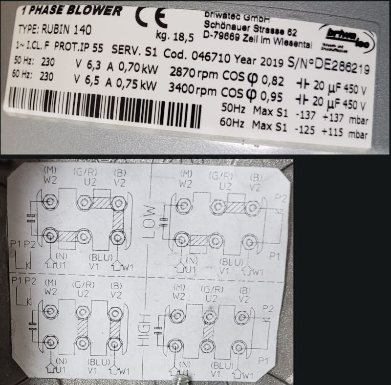
I am trying to troubleshoot a machine that has a blower with a single phase motor. The manufacturer of this machine sent us this blower as a replacement for a different one that had worked fine for quite some time, but then failed. The nameplate and wiring diagram for the new blower are shown below ...

... The wiring for this new blower/motor is different than that for the one we are trying to replace. I know that the old blower worked when we applied 205 VAC across two of the motor terminals, without requiring us to do anything else. The manufacturer told us that this new blower should work if we follow the "High" diagram on the wiring diagram and apply 205 VAC across terminals U1 and W1. There are actually two "High" diagrams. The one on the left shows a jumper between terminals W1 and V2. The one on the right shows wires labeled "P1" and "P2" connected to W1 and V2. At the end of P2, there is a triangle that appears to be making contact with a line at the end of P1.
Currently, I have no documentation on this blower other than what I have shown above. I have requested information from the blower manufacturer, but I was wondering if anyone here might be able to tell me what this P1/P2 connection might be?
Any suggestions will be greatly appreciated.
Thanks in advance,
Paul
I am trying to troubleshoot a machine that has a blower with a single phase motor. The manufacturer of this machine sent us this blower as a replacement for a different one that had worked fine for quite some time, but then failed. The nameplate and wiring diagram for the new blower are shown below ...

... The wiring for this new blower/motor is different than that for the one we are trying to replace. I know that the old blower worked when we applied 205 VAC across two of the motor terminals, without requiring us to do anything else. The manufacturer told us that this new blower should work if we follow the "High" diagram on the wiring diagram and apply 205 VAC across terminals U1 and W1. There are actually two "High" diagrams. The one on the left shows a jumper between terminals W1 and V2. The one on the right shows wires labeled "P1" and "P2" connected to W1 and V2. At the end of P2, there is a triangle that appears to be making contact with a line at the end of P1.
Currently, I have no documentation on this blower other than what I have shown above. I have requested information from the blower manufacturer, but I was wondering if anyone here might be able to tell me what this P1/P2 connection might be?
Any suggestions will be greatly appreciated.
Thanks in advance,
Paul
