Continue to Site

Eng-Tips is the largest engineering community on the Internet

Intelligent Work Forums for Engineering Professionals

  • Congratulations MintJulep on being selected by the Eng-Tips community for having the most helpful posts in the forums last week. Way to Go!

Moving Heat Flux (laser) - From the simplest example - DFLUX subroutine 4

Status
Not open for further replies.

polak7

Materials
Jan 23, 2015
52
Hello,
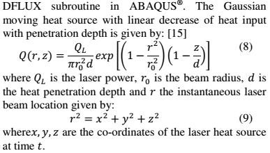
I have to write the DFLUX subroutine for moving heat flux (laser, described by Gaussian equation). It should be "volumetric heat flux". I am novice in writing subroutines. It is first in my life.

Here is the equation:
equation_jhwnsr.png

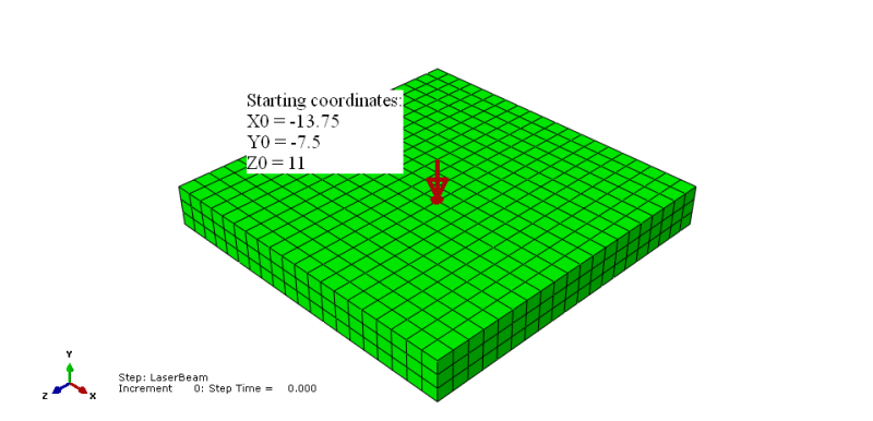
And here is the figure of substrate, on which the heat flux is applied:
Substrate2_jtrdj5.png


Starting coordinates of the beam are (mm are used in whole model):
X0 = -13.75 [mm]
Y0 = -7.5 [mm]
Z0 = 11 [mm]

Characteristics of laser:
Scanning speeds: 4-6mm/s
Laser power: 120W
Laser spot size: 1-1.2mm at diameter
Focus distance: 5mm


DFLUX subroutine:
Because of the fact, that I do not have experience in writing subroutines, I want to start from the easiest case. First, I want to define heat flux without moving (stationary):

Code:
      SUBROUTINE DFLUX(FLUX,SOL,KSTEP,KINC,TIME,NOEL,NPT,COORDS,
     1 JLTYP,TEMP,PRESS,SNAME)
C
      INCLUDE 'ABA_PARAM.INC'
C
      DIMENSION FLUX(2), TIME(2), COORDS(3)
      CHARACTER*80 SNAME

      QL=120000.d0                        !LASER POWER [mW]
      R0=0.6d0                            !BEAM RADIUS [mm]
      DEPTH=5.d0                          !PENETRATION DEPTH [mm]
      Q=(QL/(R0**2*3.1415926d0*DEPTH))    !BODY FLUX [mW/mm^3] ?
      V=5.d0                              !LASER BEAM VELOCITY [mm/s]
      
      X0=-13.75d0                         !STARTING COORDINATE OF THE LASER BEAM
      Y0=-7.5d0                           !STARTING COORDINATE OF THE LASER BEAM
      Z0=11d0                             !STARTING COORDINATE OF THE LASER BEAM

      FLUX(1)=Q

      RETURN
      END

The first problem is, that the heat affect whole surface, not the coordinates X0, Y0, Z0. I suppose, that the X0, Y0 and Z0 coordinates should be included in some way into FLUX(1) line. I saw other examples of moving heat flux on the Internet, but they are too complicated for me at the moment. I want to understand the code.

Maybe someone will explain me, what should I add to the code?
 
Replies continue below

Recommended for you

V, X0, Y0, Z0 are doing nothing in your subroutine. You should have some kind of IF statement that says that if the coordinates are within a range then the flux=whatever, else is zero, and where the coordinate position is dependent upon time.

 
Corus, thanks for your answer.

The upgraded code is presented below:

Code:
      SUBROUTINE DFLUX(FLUX,SOL,KSTEP,KINC,TIME,NOEL,NPT,COORDS,
     1 JLTYP,TEMP,PRESS,SNAME)
C
      INCLUDE 'ABA_PARAM.INC'
C
      DIMENSION FLUX(2), TIME(2), COORDS(3)
      CHARACTER*80 SNAME

      QL=120000.d0                        !LASER POWER [mW]
      R0=0.6d0                            !BEAM RADIUS [mm]
      DEPTH=0.5d0                         !PENETRATION DEPTH [mm]
      Q=(QL/(R0**2*3.1415926d0*DEPTH))    !BODY FLUX [mW/mm^3] ?
!     V=5.d0                              !LASER BEAM VELOCITY [mm/s]
      
      X0=-13.75d0                         !STARTING COORDINATE OF THE LASER BEAM
      Y0=-7.5d0                           !STARTING COORDINATE OF THE LASER BEAM
      Z0=11.d0                            !STARTING COORDINATE OF THE LASER BEAM

      X=COORDS(1)
      Y=COORDS(2) 
      Z=COORDS(3)
      
      IF(X.EQ.X0) THEN
      FLUX(1)=Q
      ELSE
      FLUX(1)=0
      END IF
      
      RETURN
      END

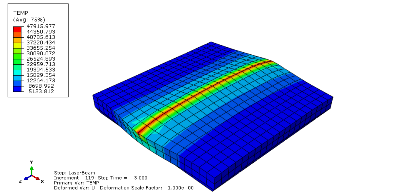
The results are:
1_rdxbga.png

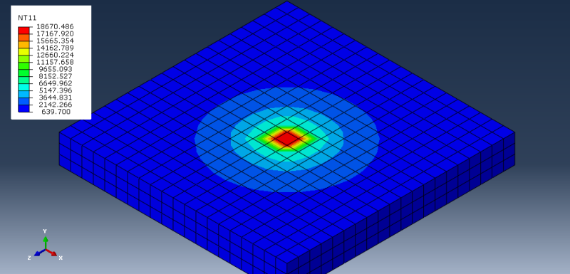
It looks good, but I don't understand why the temperature values are so big.
When I try to do the same, but with Z coordinates:

Code:
      SUBROUTINE DFLUX(FLUX,SOL,KSTEP,KINC,TIME,NOEL,NPT,COORDS,
     1 JLTYP,TEMP,PRESS,SNAME)
C
      INCLUDE 'ABA_PARAM.INC'
C
      DIMENSION FLUX(2), TIME(2), COORDS(3)
      CHARACTER*80 SNAME

      QL=120000.d0                        !LASER POWER [mW]
      R0=0.6d0                            !BEAM RADIUS [mm]
      DEPTH=0.5d0                         !PENETRATION DEPTH [mm]
      Q=(QL/(R0**2*3.1415926d0*DEPTH))    !BODY FLUX [mW/mm^3] ?
!     V=5.d0                              !LASER BEAM VELOCITY [mm/s]
      
      X0=-13.75d0                         !STARTING COORDINATE OF THE LASER BEAM
      Y0=-7.5d0                           !STARTING COORDINATE OF THE LASER BEAM
      Z0=11.d0                            !STARTING COORDINATE OF THE LASER BEAM

      X=COORDS(1)
      Y=COORDS(2) 
      Z=COORDS(3)
      
      [COLOR=#CC0000]IF(Z.EQ.Z0) THEN[/color]
      FLUX(1)=Q
      ELSE
      FLUX(1)=0
      END IF
      
      RETURN
      END

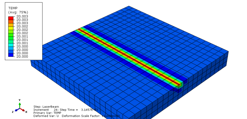
I get:
2Z_nupf7f.png


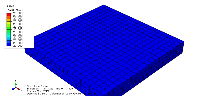
The temperature values are very small. Additionaly, above results refer to very small step time value. At the end of the simulation, there is no heat flux effect:
3Z_jkbahw.png


Then I modified the code:
Code:
      SUBROUTINE DFLUX(FLUX,SOL,KSTEP,KINC,TIME,NOEL,NPT,COORDS,
     1 JLTYP,TEMP,PRESS,SNAME)
C
      INCLUDE 'ABA_PARAM.INC'
C
      DIMENSION FLUX(2), TIME(2), COORDS(3)
      CHARACTER*80 SNAME

      QL=120000.d0                        !LASER POWER [mW]
      R0=0.6d0                            !BEAM RADIUS [mm]
      DEPTH=0.5d0                         !PENETRATION DEPTH [mm]
      Q=(QL/(R0**2*3.1415926d0*DEPTH))    !BODY FLUX [mW/mm^3] ?
!     V=5.d0                              !LASER BEAM VELOCITY [mm/s]
      
      X0=-13.75d0                         !STARTING COORDINATE OF THE LASER BEAM
      Y0=-7.5d0                           !STARTING COORDINATE OF THE LASER BEAM
      Z0=11.d0                            !STARTING COORDINATE OF THE LASER BEAM

      X=COORDS(1)
      Y=COORDS(2)
      Z=COORDS(3)
      
      [COLOR=#CC0000]IF(X.EQ.X0 .AND. Z.EQ.Z0) THEN[/color]
      FLUX(1)=Q
      ELSE
      FLUX(1)=0
      END IF
      
      RETURN
      END

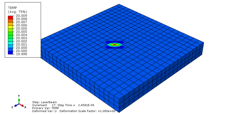
And I got:
4_dm6izd.png

It looks good, but the temperature values are very low. Again these results refer to small step time. When it grows, the heat flux effect dissapears.

What about Y coordinates? Should I define them? In a load module, as a picked region, I have chosen the top surface. There is one Y coordinate for the top surface.

How can I change the code to obtain correct results?
I attach my CAE file. Maybe it will be helpful.
CAE:
 
Are you aware that you just get energy entered, when an integration point of an element surface is exactly at your X0 and Z0 coordinates?
 
Yes, but this energy enters right at the beginning of the step. Next, it disappears. Why it disappears?
 
Maybe the integration point moves a little bit because of thermal expansion. But only if you do a fully-coupled analysis.
 
You were right Mustaine3. I removed the thermal expansion coefficient and it works very good now.
So what is the best way to control the area, on which the laser beam works?

I thought of using the followng code:

Code:
      SUBROUTINE DFLUX(FLUX,SOL,KSTEP,KINC,TIME,NOEL,NPT,COORDS,
     1 JLTYP,TEMP,PRESS,SNAME)
C
      INCLUDE 'ABA_PARAM.INC'
C
      DIMENSION FLUX(2), TIME(2), COORDS(3)
      CHARACTER*80 SNAME

      QL=120000.d0                        !LASER POWER [mW]
      R0=0.6d0                            !BEAM RADIUS [mm]
      DEPTH=0.5d0                         !PENETRATION DEPTH [mm]
      Q=(QL/(R0**2*3.1415926d0*DEPTH))    !BODY FLUX [mW/mm^3] ?
!     V=5.d0                              !LASER BEAM VELOCITY [mm/s]
      
      X0=-13.75d0                         !STARTING COORDINATE OF THE LASER BEAM
      Y0=-7.5d0                           !STARTING COORDINATE OF THE LASER BEAM
      Z0=11.d0                            !STARTING COORDINATE OF THE LASER BEAM

      X1=-12.75d0
      Z1=-6.5d0
      
      X=COORDS(1)
      Y=COORDS(2)
      Z=COORDS(3)
      
      [COLOR=#EF2929]IF(X.GT.X0 .AND. X.LT.X1 .AND. Z.GT.Z0 .AND. Z.LT.Z1) THEN[/color]
      FLUX(1)=Q
      ELSE
      FLUX(1)=0
      END IF
      
      RETURN
      END

But this code doesn't work. How can I make it work?
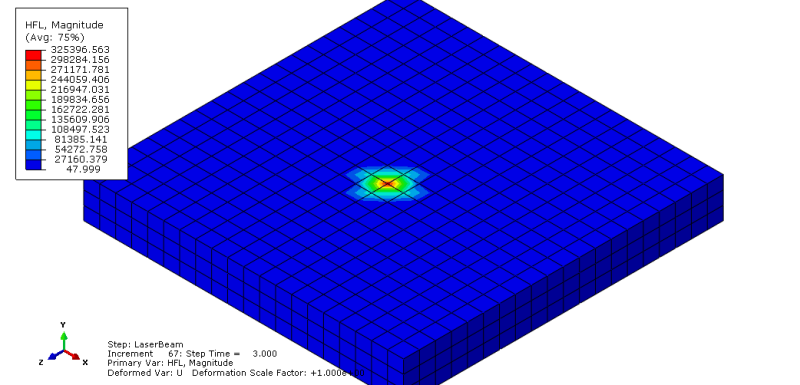
And why the values of heat flux density are so huge?:
heatf_qkzuk4.png
 
I refresh the topic again.
How can I expand the heat flux affected area?
 
Check your IF formula again. I think it will never be fulfilled with your data.
 
You are right, but I know, that IF formula is a problem.
I do not have an idea how to modify it to obtain desired expanded heat flux affected area.
 
I did few mistakes in that subroutine.

I had:
X0=-13.75d0
Y0=-7.5d0
Z0=11.d0
X1=-12.75d0
Z1=-6.5d0

Code:
IF(X.GT.X0 .AND. X.LT.X1 .AND. Z.GT.Z0 .AND. Z.LT.Z1) THEN

In that formula I have an operator .GT. an .LT.
So, the X0 and X1 values are not taken into account. There are no nodes (first coordinate of the nodes) between X0 and X1, because the distance between two nodes equals 1.

The next mistake concerns the Z coordinate:
I have: Z.GT.Z0
It should be: Z.LTZ0

I have: Z.LT.Z1
It should be: Z.GT.Z1

So, the final subroutine is:
Code:
      SUBROUTINE DFLUX(FLUX,SOL,KSTEP,KINC,TIME,NOEL,NPT,COORDS,
     1 JLTYP,TEMP,PRESS,SNAME)
C
      INCLUDE 'ABA_PARAM.INC'
C
      DIMENSION FLUX(2), TIME(2), COORDS(3)
      CHARACTER*80 SNAME

      QL=120000.d0                        !LASER POWER [mW]
      R0=0.6d0                            !BEAM RADIUS [mm]
      DEPTH=0.5d0                         !PENETRATION DEPTH [mm]
      Q=(QL/(R0**2*3.1415926d0*DEPTH))    !BODY FLUX [mW/mm^3] ?
!     V=5.d0                              !LASER BEAM VELOCITY [mm/s]
      
      X0=-13.75d0                         !STARTING COORDINATE OF THE LASER BEAM
      Y0=-7.5d0                           !STARTING COORDINATE OF THE LASER BEAM
      Z0=11.d0                            !STARTING COORDINATE OF THE LASER BEAM

      X1=-12.75d0
      Z1=10.d0
      
      X=COORDS(1)
      Y=COORDS(2)
      Z=COORDS(3)
      
      IF(X.GE.X0 .AND. X.LE.X1 .AND. Z.LE.Z0 .AND. Z.GE.Z1) THEN
      FLUX(1)=Q
      ELSE
      FLUX(1)=0
      END IF
      
      RETURN
      END

And the result is:
HFLNT_ommfxd.png


The next step will be creating the volumetric heat flux. The aim is to create the Gaussian Distribution.
Now I will try to do this alone and I will ask for help if I will have some problems.
 
Thank you very much for your post. It is very useful. I met one problem when I use DFLUX. I tried to simulate one heat source moves as a curve. The heat source moving track is parabola, here is the function: y=x(x-1) with the constant speed of 0.002m/s. Do you have any ideas on this? Thanks.
 
Hey BruceZhang2010,

Were you able to include moving heat into your fortran code? I tried to do something similar, but it doesn't really work. Could you maybe send an idea?
Thanks
 
Status
Not open for further replies.

Part and Inventory Search

Sponsor