I'm trying to understand MSR38-D/DP. The safety relays I am familiar with has redundant chains; a (+) channel and (-) channel. Looking at the diagram, MSR38-D/DP seems to have S11 & S12 as one chain, and S21 & S22 as the other chain. So, as the picture below shows, since the chain circuits are completed, I should get 24V when I put my meter leads across S11 & S21, right? But when I did that, I get no voltage, but the relay has two green LEDs on for the two output channels.
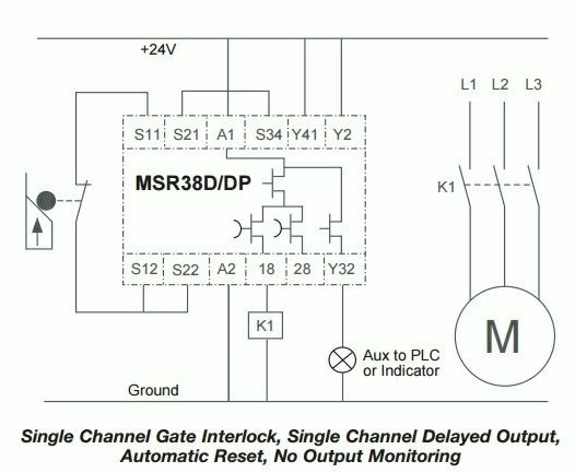
What confuses me more is the seconds diagram; how can S21 be connected to the reset (S34), and S22 connected to the (+) chain?
What confuses me more is the seconds diagram; how can S21 be connected to the reset (S34), and S22 connected to the (+) chain?