Eng-Tips is the largest engineering community on the Internet

Intelligent Work Forums for Engineering Professionals

  • Congratulations waross on being selected by the Tek-Tips community for having the most helpful posts in the forums last week. Way to Go!

Multi-layer system: Stress-strain discrepency

Status
Not open for further replies.

PhiaSmit

Civil/Environmental
May 23, 2019
2
0
0
ZA
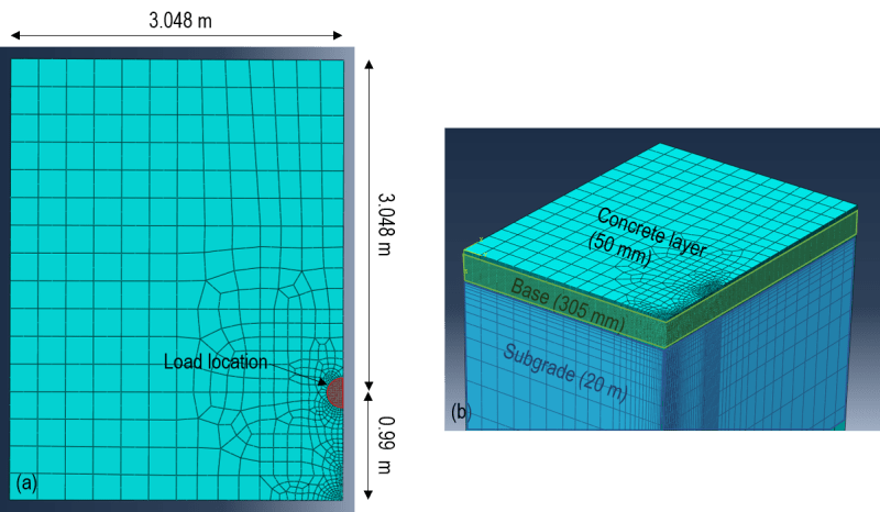
I have modelled a LE, three-layer system that consists of a 50 mm concrete layer (40 000 MPa), a 305 mm granular layer (207 MPa) and a 20 000 mm subgrade layer. The system is modelled as one part. A pressure of 550 kPa is applied to the system over a circular area. The z-axis is used as the vertical axis and C3D20R element were used.


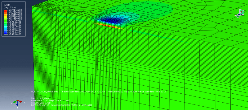
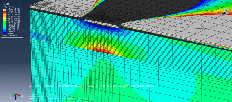
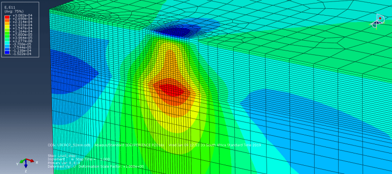
When I plot S11 the stress in the concrete layer varies from a compressive stress at the top of the layer to a tensile at the bottom of the layer. In the granular layer S11 once again varies from a compressive stress at the top to a tensile stress at the bottom. When I plot the strain with depth of the two layers it is continuous, with the neutral axis (of the system) in the concrete layer and tensile strains from the neutral axis downward.


Why would there be a discrepency between the sign of S11 and E11 in the granular layer?

Help would be appreciated

 
Replies continue below

Recommended for you

Judging by the terms you use I guess that you utilize Abaqus for this simulation. Can you share a picture of your model ? And if possible also some screenshots with stress/strain plots on the cross-section of the model. It will be easier to help if we can see this. Gor now I can only suspect that the potential error may lie in the way your model’s layers are defined. You said that this is one part so the layers must be in form of partitions. Try modeling this as separate instances with interaction between them - if it’s Abaqus you can use Merge/Cut Instances to divide that part into separate instances. Then assign an interaction between them - tie constraint or contact.
 
Good day

Yes, I am using Abaqus.

I have uploaded an image of my model. I have also uploaded screenshots of contour plots of S11 and E11, as well as S11 where I adjusted the contour limits so that you can see the contours in the base layer.

I am modelling a pavement structure. I modelled it as one part, partitioned the part into layers and then assigned different material properties to the layers. The layers share nodes in the plane between two layers.

I have modelled a similar system with seperate parts, introducing interaction between the layers. Instead of using a tie constraint, I used tangential and normal properties of "rough" and hard contact(not allowing seperation)respectively (in retrospect I should have tried a tie constraint). I have the same discrepency in terms of the sign of stress and strain not being the same at the top of the base layer.

Thank you for the suggestions. I will try the tie constraint. I intend to model a simply supported composite beam using 3D elements with the same thicknesses and E-values of the concrete layer and base layer in the pavement to see if the same issue occurs.

Please let me know if you have any more suggestions.
ModelLayout_bwfovn.png
50mm_S11_Contour_yckzfp.png
50mm_S11_ContourLimits_tlklrm.png
50mm_E11_Contour_qrcwnf.png
 
Status
Not open for further replies.
Back
Top