PhiaSmit
Civil/Environmental
- May 23, 2019
- 2
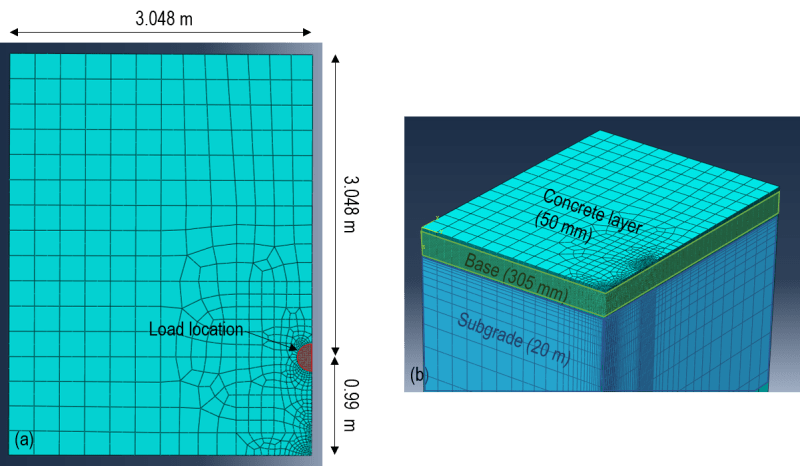
I have modelled a LE, three-layer system that consists of a 50 mm concrete layer (40 000 MPa), a 305 mm granular layer (207 MPa) and a 20 000 mm subgrade layer. The system is modelled as one part. A pressure of 550 kPa is applied to the system over a circular area. The z-axis is used as the vertical axis and C3D20R element were used.
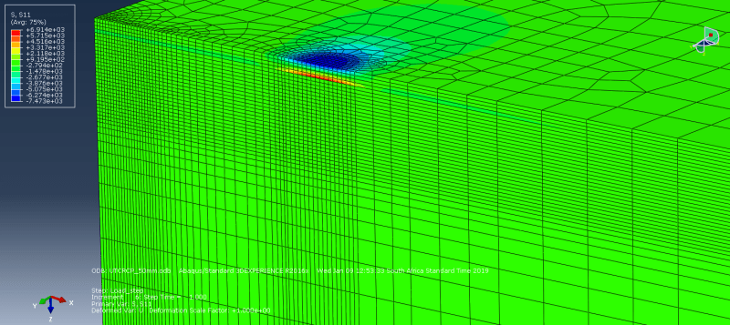
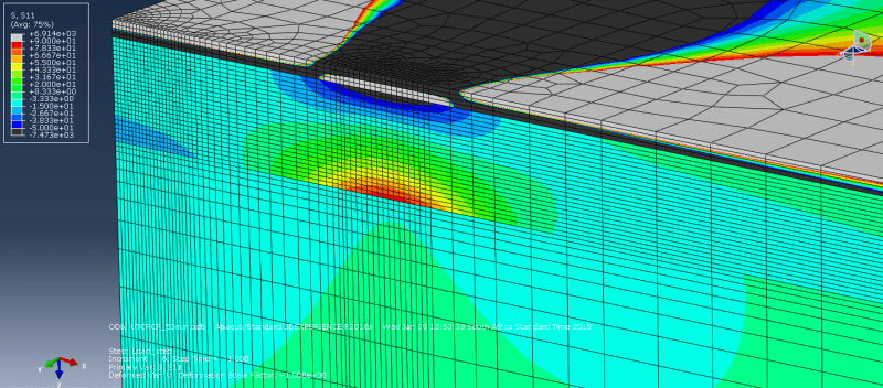
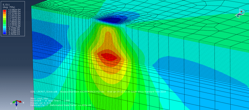
When I plot S11 the stress in the concrete layer varies from a compressive stress at the top of the layer to a tensile at the bottom of the layer. In the granular layer S11 once again varies from a compressive stress at the top to a tensile stress at the bottom. When I plot the strain with depth of the two layers it is continuous, with the neutral axis (of the system) in the concrete layer and tensile strains from the neutral axis downward.
Why would there be a discrepency between the sign of S11 and E11 in the granular layer?
Help would be appreciated