Eng-Tips is the largest engineering community on the Internet

Intelligent Work Forums for Engineering Professionals

  • Congratulations waross on being selected by the Eng-Tips community for having the most helpful posts in the forums last week. Way to Go!

Multi-output from different areas in a drill

Status
Not open for further replies.

davagusor

Industrial
Jan 27, 2021
7
ES
Hello all and thank you in advance.

I'm trying to simulate a drill with a partition (which is supposed to be the weld) and 2 materials (one per partition).

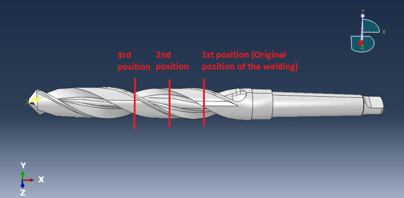
The thing is I wanted to get the stresses and strain in the original weld position, then the same outputs in the 2nd position and also in the original one, and finally in the 3rd position and again in the original one. How can I do it? I mean, I've been doing it creating 2 offset planes around the original partition plane (+-1 mm of offset) and creating a set with the partition of those 2 planes. Anyway of doing it in a easier form?

Sin_t%C3%ADtulo_ylegdb.png
 
Replies continue below

Recommended for you

If you need exact output for particular regions then the best way is to create partitions (like you did) and define node or element sets for these regions. Then add history output requests referencing previously created sets. You can also use a section cut or replace selected elements in postprocessing (so that the results are only displayed for them).
 
So no other way to extract those exact outputs without creating partitions, right? I wanted to avoid this way, because I have to create multiple partitions and because of this, apply materials to them continously... And also another point, trying to extrapolate this to and script is kinda impossible for me...

Anyway, thank you!
 
To get output at a given location you need nodes and elements aligned with this location. Partitions are necessary to ensure that nodes and elements will be created exactly there.

As I mentioned before, another way is to use proper postprocessing tools. Here you could also create path plots, this might be the best and easiest way in this case.
 
Hello again FEA way (Hope you see this, I don't know how to mention you in this forum)

It's not about getting the output of an exact area, it's about getting the outputs around an area more or less (around the partition plane).

Could you maybe give me some tips about the postprocessing tools you said? You said something about creating plot path... It sounds great!

Thank you very much again.
 
Path plot is a special type of X-Y plot that allows you to see the variation of output quantity (like stress) along the selected line. It's also the only way (apart from Python scripting) to extract results from arbitrary point of the model (by giving its coordinates), so that you aren't limited to querying nodes and integration points. Just use Tools --> Path --> Create --> Point list and enter coordinates of selected point(s). Then use Create XY Data --> Path to define a path plot.
 
Status
Not open for further replies.

Part and Inventory Search

Sponsor

Back
Top