Continue to Site

Eng-Tips is the largest engineering community on the Internet

Intelligent Work Forums for Engineering Professionals

  • Congratulations GregLocock on being selected by the Eng-Tips community for having the most helpful posts in the forums last week. Way to Go!

Multi-ply Wood Beam Fastener Calculation 1

Status
Not open for further replies.

TAB_HOO

Structural
Sep 2, 2022
6
How would you go about calculating the number/spacing of fasteners required to create a multi-ply wood beam such as a 2-2x10 with the 9.25" side vertical and the fasteners horizontal? I'm aware that there are prescriptive requirements for this situation and details provided by manufacturers such as Simpson and Weyerhaeuser, but I'm having a hard time understanding how one would do the calculations. If the multi-ply beam was oriented such that the 9.25" side was horizontal and the fasteners were vertical, one could look at the shear flow at the interface between the beams, but I'm not sure about this situation. My feeling is that fasteners wouldn't matter much if the beam was loaded from the top, but it certainly would if the beam was loaded from the face as with face-mounted joist hangers. Any help is appreciated!
 
Replies continue below

Recommended for you

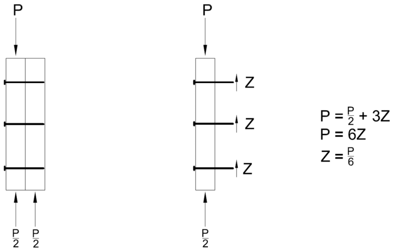
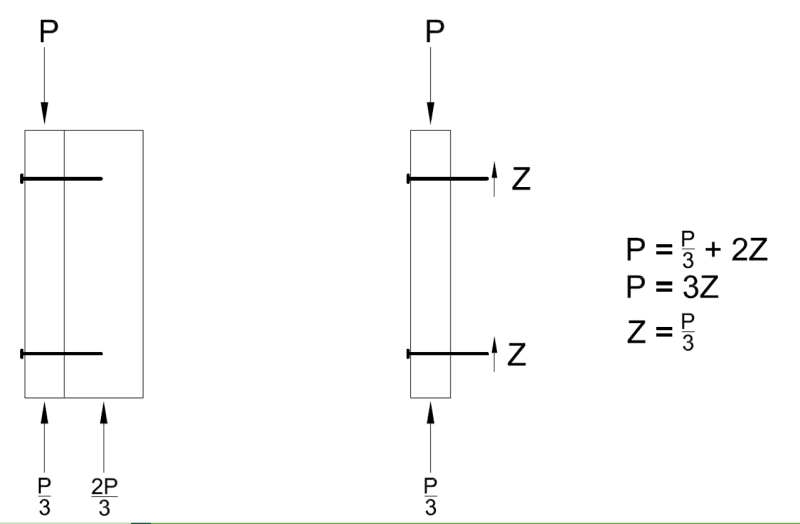
it's a fairly simple free body diagram to figure out, see below. I only included 2-ply solutions, but the same theory applies when considering additional plies.

1_lxwxor.png


2_jtprko.png
 
I may be missing something, but the way you have it drawn the moments don't sum to zero. You have a torsional moment that has to be resolved with tension in the fastener(s) and compression between the plies, right? Are the P's that are directed upward in your drawing internal shear forces?

Here are my thoughts, let me know if you think I'm wrong:
In order for the multi-ply beam to behave like a single beam, each ply has to have the same deflection. That deflection would also have to be equal to the deflection of a solid section of equivalent cross-section to the multi-ply beam. This means that the load taken by each ply would be distributed proportionally to each ply's share of the flexural rigidity (E*I) of the solid section. If the load is applied to one ply only, the portion of the load that the other plies are "responsible for" must be transferred through the fasteners to the other plies? Does that make sense? I'm still not sure about the torsional moment though.
 
@TAB HOO

I use the proportionality of EI/L when needed for this. Never considered the fasteners resisting the torsional moment.

If you are just sistering the same plies of lumber then EI is consistent and you get easy distributions otherwise I come up with factors based on the ratio of EI.

Simpson uses has a screw specifically for fastening this, and they show increased fasteners at locations of point loads, and also differentiate between top loaded, front face loaded, and back face loaded.

I generally try to come up with a pattern that avoids needing special detail at different locations. But sometimes you may waste a lot of effort getting that to work.

 
TAB_HOO said:
the way you have it drawn the moments don't sum to zero
I suppose fundamentally you are correct, we are assuming an analysis for shear only. What's the magnitude of the torsional load onto such a member, and is the local pull-out a bigger concern than global torsional stability of the built-up member? Generally speaking, the torsional load is limited.
If we assume a worst case scenario, where joists are hangered into the side of one of the plies, we induce an eccentric load, but the joists that are hangered also provide torsional restraint. The built-up beam should also be braced for LTB checks by the designer.

TAB_HOO said:
Are the P's that are directed upward in your drawing internal shear forces?
The 'P' at the top is the force we are calculating for, the 'P' at the bottom is the reaction that is assumed to be resolved through each member. For the 2-ply member of matching thickness, I assume each ply has the same EI, and therefore, half the load is resolved as a reaction in the left ply, and half the load is resolved in a reaction on the right ply.
For the second example where one ply is larger, I ratio the reaction based on the EI, since the right member is twice as thick, it carries twice as much load.
The 'P' that is directed upward is intended to show the load that stays within the ply, and is not transferred through the fasteners to the adjacent ply.

TAB_HOO said:
In order for the multi-ply beam to behave like a single beam, each ply has to have the same deflection.
Correct. The load is transferred as shear through the fasteners. The fasteners are only responsible to transfer the load that is to be carried by the unloaded plies. The fasteners do not need to transfer all of the load experienced by the outer ply, since the outer ply will support some of the loading with or without the fasteners.
 
You might be careful with this one...

Clipboard01_d25f5n.png


-----*****-----
So strange to see the singularity approaching while the entire planet is rapidly turning into a hellscape. -John Coates

-Dik
 
Varies so much with the loading, the support, and the interconnection.

-----*****-----
So strange to see the singularity approaching while the entire planet is rapidly turning into a hellscape. -John Coates

-Dik
 
I know built-up columns are specifically covered in NDS 15.3...not sure about beams though.
 
Leceid, I've looked in NDS and haven't been able to find anything.

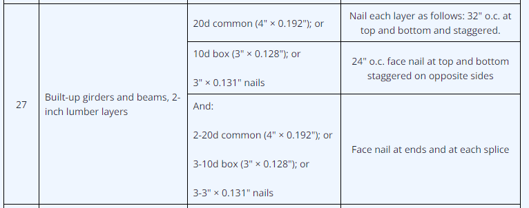
Table R602.3(1) in the 2018 IRC has the following:
table_fdbcto.png


The 2018 IRC R507.5 Deck Beams states the following:
deck_beams_auooiw.png
 
TAB_HOO: yep, those are the bare minimums. Regardless of your calculations, the fastening between plies should be at least what is in the IRC table (or IBC table if it's a commercial job). But if you calculate the need for more - side loaded beam, point loads, etc. - then you have to put more in.

Chorasden's image is really good. I usually specify construction adhesive between the plies as well. The torsion is typically minimal unless you're dealing with a 4 or 5 ply side loaded beam. In that case, use screws or ring shank nails in lieu of smooth shank nails. That plus the adhesive is enough for me to not concern myself with it.

Times I do think about it: up-stand beams in an attic that don't have their top edge continually braced, grillage type arrangements, or other less-than-traditionally-braced applications.
 
Status
Not open for further replies.

Part and Inventory Search

Sponsor