Eng-Tips is the largest engineering community on the Internet

Intelligent Work Forums for Engineering Professionals

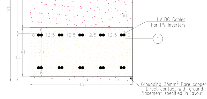
Multilayer of LV cables directly in the ground

Status
Not open for further replies.

Vlad.M

Electrical
Feb 14, 2024
7
0
0
IL
Hi guys,

Is there a right way to calculate the reduction factor like in table B.52.18 as in standard IEC 60364 but for 2 layers of cables?
Screenshot_2_bjgg1w.png


is it possible that in official standard there are no guide line for that case?

cheers.
 
Replies continue below

Recommended for you

You are right. For one row of 5 cables, you can use the tables, but not for two rows.
A remark about IEC 60364-5-52 standard at first.
Annex B it is only informative, and the ampacities shown here are in order to exemplify a new mode of presentation and these are not correct values.
The A annex is still for calculations. See, at first one of the following tables:
Table A.52-2 (52-C1) – Current-carrying capacities in amperes for methods of installation in table A.52-1 (52-B1) – PVC insulation/two loaded conductors/copper or aluminum Conductor temperature: 70 °C/Ambient temperature: 30 °C in air, 20 °C in ground –column D, or:
Table A.52-3 (52-C2) – Current-carrying capacities in amperes for methods of installation in table A.52-1 (52-B1) – XLPE or EPR insulation/two loaded conductors/copper or aluminum Conductor temperature: 90 °C/Ambient temperature: 30 °C in air, 20 °C in ground –column D.
And then see:
Table A.52-18 (52-E2) – Reduction factors for more than one circuit, cables laid directly in the ground –
for 5 cables [of 2 conductors] 0.125 m apart. kred=0.65
For two rows of 5 cables per each row you have to calculate the current carrying capacity according
to IEC 60287-2-1 [and 1-1].
 
Table A.52-3 (52-C2) is calculated per IEC 60287-2-1 and 1-1.
The column D it is for 2 cables in a duct in 2.5 K.m/W Earth thermal resistivity and 0.7 m depth in a duct.
Reference method D, item 70 of table 52-3, (multi-core cable in ducts in the ground):
Cable drawn into plastic, earthenware or metallic ducts laid in direct contact with soil having a thermal resistivity of 2.5 K.m/W and a depth of 0.7 m.
According to your sketch there are two single core cables touching but without any pipe [or duct].
[so Rsd=0 and 110 cm depth]. Let’s say the resistivity stays 2.5 K.m/W.
The calculation according to IEC 60287-2-1 is very simple taking into consideration the cable data-conductor diameter 15 mm, insulated core diameter 17.8 mm and the jacket diameter of 21.2 mm.
The ampacity -per each cable-is then 120.7A.
Following DIN-VDE [from ABB vol.11-E-13] table 13-44, for 3 single core cables in triangle, aluminum I=305 A. From table 13-54 for XLPE, 20oC, 2.5 K.m/W, load factor 1[100%] f1=0.81. From table 13-56 for 10 systems 7cm apart f2=0.44. Then for 10 groups of 3 cables we get 305*0.81*0.44=108.7 A

 
 https://files.engineering.com/getfile.aspx?folder=285267e1-53d1-4773-a92d-fbe14aa9957f&file=ABB__11-E-13_Table_13-44.jpg
interesting, thank you for the explanation.
if it is not too much to ask, can you please share the tables: Table A.52-3 (52-C2) and table 52-3?

appreciate your help.
 
Status
Not open for further replies.
Back
Top