Vlad.M
Electrical
- Feb 14, 2024
- 7
Hi guys,
Is there a right way to calculate the reduction factor like in table B.52.18 as in standard IEC 60364 but for 2 layers of cables?
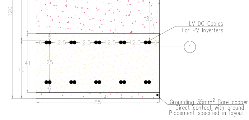
is it possible that in official standard there are no guide line for that case?
cheers.
Is there a right way to calculate the reduction factor like in table B.52.18 as in standard IEC 60364 but for 2 layers of cables?
is it possible that in official standard there are no guide line for that case?
cheers.