Eng-Tips is the largest engineering community on the Internet

Intelligent Work Forums for Engineering Professionals

Multiple 11kV 2.5MVA emergency standby Generators - Earthing strategy 1

Status
Not open for further replies.

tofulover

Electrical
Jun 17, 2020
40
0
0
AU
Hi all,

I have a system with 3 off 11kV 2.5MVA emergency standby generators that will be supplying emergency power to a critical facility when the network power from the utility is disrupted.

The connections go like this:

3 off 11kV generators -> 11kV generator bus -> 11kV ring mains serving various substations in the ring.

In terms of earthing strategy this is what I am proposing:

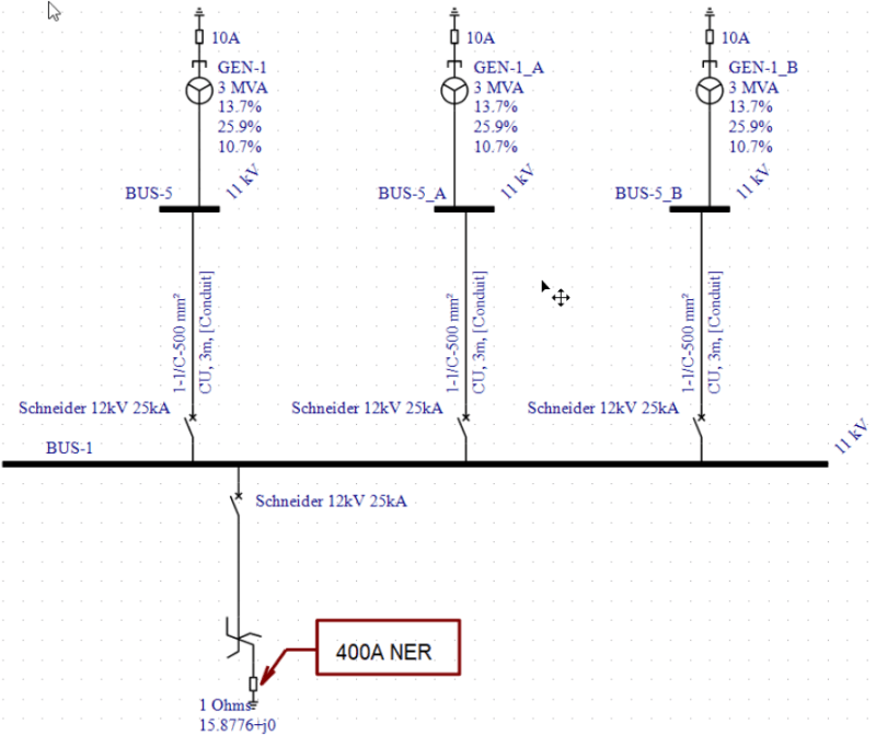
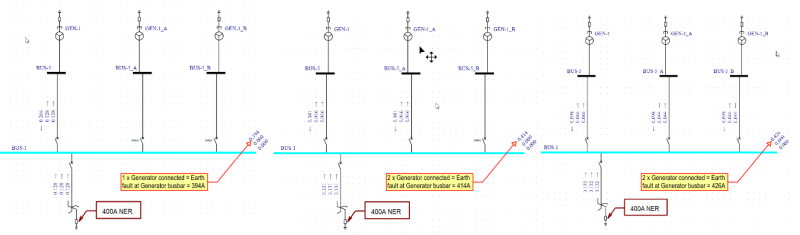
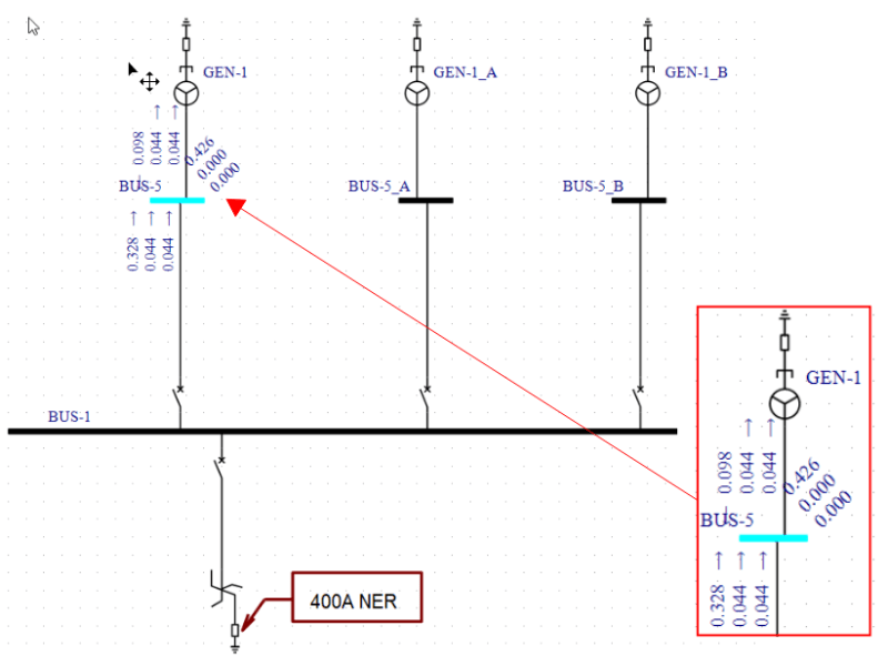
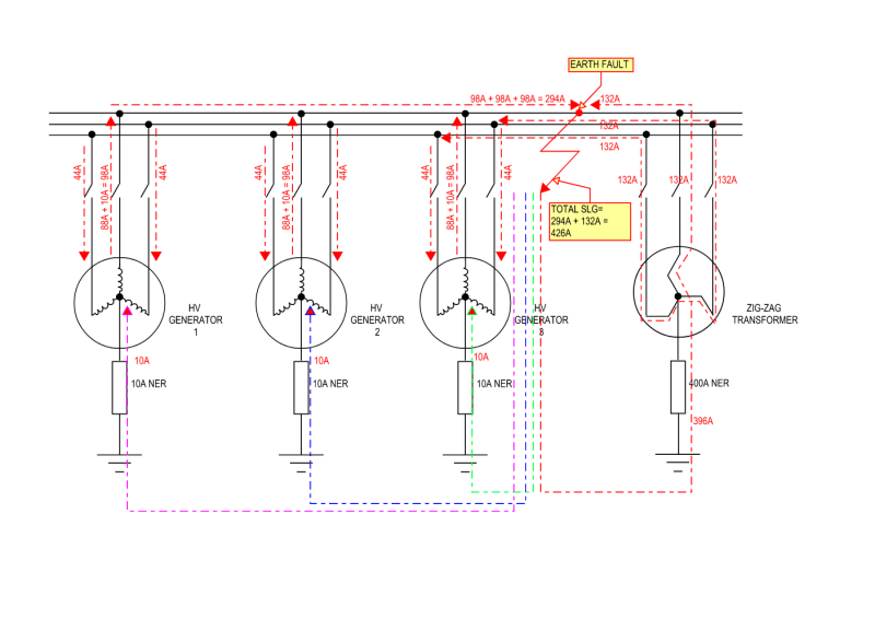
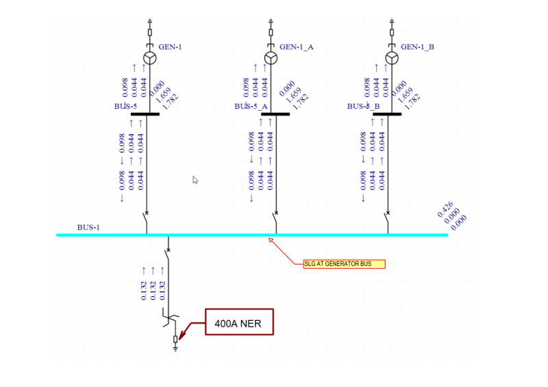
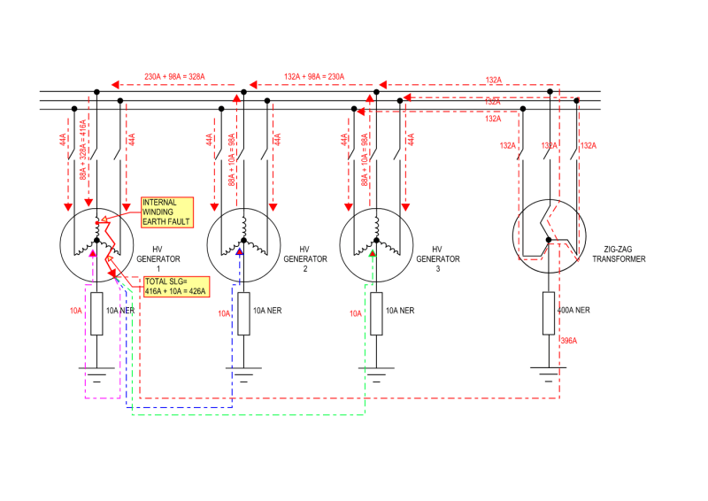
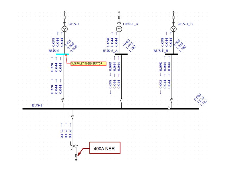
1) Each of the 11kV generator to be provided with an NER sized to limit earth fault current to 10A - to limit damage to the stator during an earth fault, esp once the field is disconnected and the machine is slowing down - my understanding is that this is the time where the stator takes the most damage.

2) To handle normal earth fault within the 11kV network, a zigzag transformer with an NER sized to earth fault current of 400A will be used. This zigzag transformer will be connected to the 11kV generator bus.

3) The generator bus will be provided with a circuit breaker such that it is disconnected from the network when the power supply from the authority is live - otherwise the zigzag transformer will become a remote earth to the supply authority's incoming feeder.

I have checked the cable capacitance charging current of the 11kV network and the extent of this charging current is low, given the physical length of the cables are not really that long.

Could I please gather some comments/feedback if the above earthing strategy for the 11kV generator is sound?

Thanks
Tofu
 
Replies continue below

Recommended for you

Since you have mentioned 11kV, I believe that you have to follow IEC stds.
Therefore, my preference is to have a LRG system with an allowable earth fault current of about 200A.
So the NGR has to be sized accordingly.
Alternatively,
1) you can have a HRG system with a distribution transformer at the neutral.
If your 11kV system does not have much cable capacitance current then 10A is reasonable at
11kV. Hence you have to size the distribution transformer accordingly.
2) you may have a HRG system with a NGR sized for 10A
From my experience using a zig-zig is little bit costly and complicated because you have to provide
protection for that too.
All in all LRG with a coordinated earth fault protection system is preferred.
 
The grounding transformer on the bus will predominate.
Any ground faults on either the system or on a connected generator will be limited by the 400 Amp NGR.
The neutral grounding of the individual generators will become active when the generator breaker is opened.
Once your differential protection trips the generator off-line due to differential currents the ground fault current will be limited by the neutral grounding resistor to 10 Amps.
You may consider reducing this current.

Bill
--------------------
"Why not the best?"
Jimmy Carter
 
Kiribanda said:
Since you have mentioned 11kV, I believe that you have to follow IEC stds.
Therefore, my preference is to have a LRG system with an allowable earth fault current of about 200A.
So the NGR has to be sized accordingly.
Alternatively,
1) you can have a HRG system with a distribution transformer at the neutral.
If your 11kV system does not have much cable capacitance current then 10A is reasonable at
11kV. Hence you have to size the distribution transformer accordingly.
2) you may have a HRG system with a NGR sized for 10A
From my experience using a zig-zig is little bit costly and complicated because you have to provide
protection for that too.
All in all LRG with a coordinated earth fault protection system is preferred.

Thanks kiribanda. I am in Australia so yes we will have to follow the IEC standard pretty much but there is very little guidance from the IEC what should/should not do for the HV generator earthing - If you know any suitable standards please let me know.

So the bulk of the current proposal is heavily borrowed from the IEEE - which mentioned that the generator is easily damaged by a current of 200A. I also draw some reference from this IEEE whitepaper

Any further thoughts?

Edit: was just googling and came across this document from i-gard.com
I think figure 5 of this document is quite similar to my proposed setup.
 
waross said:
The grounding transformer on the bus will predominate.
Any ground faults on either the system or on a connected generator will be limited by the 400 Amp NGR.
The neutral grounding of the individual generators will become active when the generator breaker is opened.
Once your differential protection trips the generator off-line due to differential currents the ground fault current will be limited by the neutral grounding resistor to 10 Amps.
You may consider reducing this current.

Thanks waross. Just trying to get my head around what you commented.

if I have an 10A NER to each generator and a 400A NER to the generator common bus, and therefore any earth fault will be limited to 400A but would the 10A NER to the generator not also limit the earth fault seen by the generator to 10A - and in the process protecting the generator?

I don't quite understand what you mean when the generator breaker is opened the neutral grounding of the generator will become active. I was of the understanding that if the generator breaker is opened, no earth fault current will return via the NER associated with that generator?


In the event of an earth fault on the system the earth fault current will be 400 Amps plus 10 Amps from each generator that is online.
In the event of an earth fault in a generator the initial fault current will be determined by the 400A NRG on the bus.
The bus NRG will shunt out the generator NRG.
Once the generator trips offline, the generator fault current will be limited by the generator 10 Amp NRG.


Bill
--------------------
"Why not the best?"
Jimmy Carter
 
waross said:
In the event of an earth fault on the system the earth fault current will be 400 Amps plus 10 Amps from each generator that is online.
In the event of an earth fault in a generator the initial fault current will be determined by the 400A NRG on the bus.
The bus NRG will shunt out the generator NRG.
Once the generator trips offline, the generator fault current will be limited by the generator 10 Amp NRG.

Thanks waross for that explanation.

In this case would you think that the solution of putting a 10A HRG for the generator and a 400A LRG for the zigzag is the way to go for the generator system as mentioned?

 
NRG grounding of multiple generators presents a quandary that has been discussed in these fora before.
If the generators are each supplied with an NRG, the ground fault current may depend on the number of generators on-line.
This may complicate or defeat protection systems.
I think that your solution is a good compromise.
Your ground fault current may vary between 410 Amps with one generator on-line to 430 Amps with three generators on-line.
This small variation should not compromise protection systems.
Once the differential protection disconnects a generator with an internal fault, the destructive internal fault current will be limited to 10 Amps by the generator NGR.
Hopefully the differential protection will operate in the early stages of breakdown and the generator internal fault current may not reach 400+ Amps.
But there are a lot of good people on this forum.
There may be issues that I have inadvertently overlooked.

Bill
--------------------
"Why not the best?"
Jimmy Carter
 
waross said:
NRG grounding of multiple generators presents a quandary that has been discussed in these fora before.
If the generators are each supplied with an NRG, the ground fault current may depend on the number of generators on-line.
This may complicate or defeat protection systems.
I think that your solution is a good compromise.
Your ground fault current may vary between 410 Amps with one generator on-line to 430 Amps with three generators on-line.
This small variation should not compromise protection systems.
Once the differential protection disconnects a generator with an internal fault, the destructive internal fault current will be limited to 10 Amps by the generator NGR.
Hopefully the differential protection will operate in the early stages of breakdown and the generator internal fault current may not reach 400+ Amps.
But there are a lot of good people on this forum.
There may be issues that I have inadvertently overlooked.

Thanks again Waross.

I have carried out a quick analysis using hand-calc and via EasyPower. Could you please have a look below...

I am using a 3MVA LeroySomer alternator as an example here and the data sheet indicated the following:

X"d = subtransient reactance = 13.7% on 3MVA base = X1 = X2
X0 = zero sequence reactance = 10.7% on 3MVA base

Assume Sbase = 3MVA and Vbase = 11kV, therefore Ibase = 3MVA/(sqrt(3) x 11) = 157.43A.

Assuming that the generator is solidly grounded, a quick hand calc gives me a line to ground fault of (3 x Eln)/(X1 + X2 + X0) = 3/0.381 = 7.87pu = 7.87 x 157.43A = 1239A.

EasyPower calculate this also as 1239A. I have inserted a zigzag Tx but i have "opened" the circuit breaker.

3MVA_generator_-_solidly_grounded_-_earth_fault_nwooge.png


So I think I am on the right track.

Next I added a 10A NER to the generator and no surprise, the earth fault as seen by the generator becomes limited to 10A.

3MVA_generator_-_10A_NER_-_earth_fault_y8mf6q.png


Then I close the CB for the ZigZag (already fitted with a 400A NER) and the fault at the generator busbar now become limited by the zigzag and is circa 400A. The current flows on the zigzag during earth fault shows 3 x phases of the same magnitude which is in line with my understanding of how zigzag TX is supposed to work - when it sees an earth fault, it transpose the earth fault via 3 equal currents on 3 phases.

3MVA_generator_-_10A_NER_with_ZigZag_400A_NER_earth_fault_robpbt.png


I could not get the model to give 410A earth fault when 1 generator is online.

Just wondering if it is something I overlook in the model.

Any thoughts please?
 
So presumably you have chosen a 15.88ohm NER to get your 400A? The Easypower calc will have also taken into account the impedance of the ZigZag, hence 384A, not 400A. Add in the 10A from the Gen = 394A at the Bus..........not quite the theoretical 410A, but the 10A contribution from the Generator has been added at the bus as Waross predicted. Problem you have is that a Stator fault in this configuration also results in an SLG fault of ~394A before the Gen breaker trips, so possibly burned beyond repair anyways.
 
ppedUK said:
So presumably you have chosen a 15.88ohm NER to get your 400A? The Easypower calc will have also taken into account the impedance of the ZigZag, hence 384A, not 400A. Add in the 10A from the Gen = 394A at the Bus..........not quite the theoretical 410A, but the 10A contribution from the Generator has been added at the bus as Waross predicted. Problem you have is that a Stator fault in this configuration also results in an SLG fault of ~394A before the Gen breaker trips, so possibly burned beyond repair anyways.

Thanks pped.

I actually size the NER the zigzag TX based on 11kV/Sqrt(3) = phase voltage then divide this by 400A to get 15.8877 ohms thereabout. This is what I put into the EasyPower input.

I am unclear why you would say that the SLG of 394A will cause the genset to burn beyond repairs? Isnt this the main purpose of the 10A High resistance NER which limit the earth fault current seen by the generator to 10A?

When the main generator bus is faulted, phase A on the generator bus will see 400A and the generator will be supplying 266A into the phase A fault (so this is seen as an overcurrent) but the current returned via the neutral of the generator should still be limited to 10A? Is my understanding incorrect? If so, then this in a way negate the recommendations from IEEE to implement HRG for generators and in many cases hybrid earthing (HRG + LRG) - which is essentially what a 10A Generator NER + a 400A ZigZag Tx NER is also providing?

Could you provide some commentary to the above please?


The purpose of limiting ground fault current using LRG or HRG in a generator is REDUCE damage to the generator in the event of a ground fault in the generator. A ground fault external to generator isn't the main concern. There is no way to completely eliminate damage to the generator if the fault is in the generator. The goal is prevent damage to the core.

As waross pointed out, if you have a 400 A ground source on this bus, this, to a large degree, defeats the protection of limiting fault current to 10 A at the generators, since you will have 400 A of fault current into the generator for generator ground faults until the generator breaker opens.

Several years ago, an IEEE working group proposed a hybrid generator grounding system that could automatically switch between HRG and LRG depending on fault location. This requires a vacuum contactor to switch on the LRG resistor for external faults. Complicated solution, but illustrates one approach.


One important factor will be how critical it is to maintain generator power to your system. If you're willing to trip everything off for any ground fault, then make everything HRG. If you must have selective coordination, then LRG will work much better. Systems such as this have been installed with LRG on each generator for decades and decades. It's extremely common in the US in mills and other facilities with local power generation. In general, the goals of protection and coordination are in direct conflict, so it's always a compromise.

I'm not familiar with IEC requirements, so I may be totally missing some important issues related to codes.

Cheers,

Dave
 
dpc said:
The purpose of limiting ground fault current using LRG or HRG in a generator is REDUCE damage to the generator in the event of a ground fault in the generator. A ground fault external to generator isn't the main concern. There is no way to completely eliminate damage to the generator if the fault is in the generator. The goal is prevent damage to the core.

As waross pointed out, if you have a 400 A ground source on this bus, this, to a large degree, defeats the protection of limiting fault current to 10 A at the generators, since you will have 400 A of fault current into the generator for generator ground faults until the generator breaker opens.

Several years ago, an IEEE working group proposed a hybrid generator grounding system that could automatically switch between HRG and LRG depending on fault location. This requires a vacuum contactor to switch on the LRG resistor for external faults. Complicated solution, but illustrates one approach.


One important factor will be how critical it is to maintain generator power to your system. If you're willing to trip everything off for any ground fault, then make everything HRG. If you must have selective coordination, then LRG will work much better. Systems such as this have been installed with LRG on each generator for decades and decades. It's extremely common in the US in mills and other facilities with local power generation. In general, the goals of protection and coordination are in direct conflict, so it's always a compromise.

I'm not familiar with IEC requirements, so I may be totally missing some important issues related to codes.

Thanks Dave for your comments.

Although I work in the IEC world, sadly for HV earthing of generator there are no known IEC standards or references I can draw upon. I stand corrected so if anyone has a suitable IEC references please do tell.

The current HV generator earthing design is drawn heavily based on the IEEE standards and the scheme I am proposing is actually the exact same as figure 7 of the I-Gard whitepaper. Here is a screenshot for easy reference:
I-gard_olk7bf.png


I understand about the hybrid HRG and LRG earthing that you mentioned in your post - this would have been perfect for a single generator system - but I have a 3 generators setup.

The maximum earth fault current in this hybrid scheme would be 400A LRG + 10A HRG = 410A (I totally agree) - and further reaffirmed by I-gard as "The ground fault current would be limited to the sum of the low impedance system and the high impedance system. In the case shown the ground fault current would be 410A."

However, given I have a 3 generators setup, I-gard whitepaper noted: "When multiple units are placed on line and each unit is protected by the hybrid system, the tendency will be to have all
hybrids identical. This would cause extremely high ground fault current when the system is in low impedance, and the benefits would be lost. To compensate for this, the schematic can be reconfigured to that of Fig. 7 and all the benefits would once again be experienced.
"

I-gard further indicated a scheme which I heavily borrowed from - Generators each provided with a HRG 10A and a Zigzag with a 400A LRG. I-Gard provided the commentary as follows:

"This schematic indicates that the maximum ground fault current is in the order of magnitude of 400A., regardless of how many sources are connected to the system. Ground faults downstream will be isolated by the breaker closest to the fault by selective coordination and ground faults within the stator will be isolated by the differential scheme shown in Fig. 6, but isolation will only occur in the supply breaker for that particular breaker. This will leave the generator in a high impedance grounded state and minimize the damage to the stator."


So my understanding of the above paragraph is that:

1. When the earth fault is originated within the generator, the differential protection must isolate the generator from the generator bus - this will leave the generator standalone with its own 10A HRG NER which will then permit the generator to minimize damage to the core.

2. When the earth fault is outside the generator (say the generator bus), the maximum earth fault current is 400A.

The things I would like clarification is this:

a) Waross indicated that this 400A should really be 410A - I am not disagreeing - just trying to make sure my model in easypower is setup correctly.

b) I still don't understand why when the generator bus has a 400A earth fault, that this 400A earth fault will be coming into the generator. Based on what I understand, when there is an earth fault, the bulk of the earth fault is being taken up by the zigzag transformer with its 400A LRG and this earth fault is then transpose to 3 equal magnitude fault current on the phases. The generator will still see a return earth fault current via its 10A HRG but that will then limit the returning earth fault via its neutral to 10A.

Your comments are greatly appreciated.

Thanks again.
 
OK, I looked at your one-line more closely and as you say, it would work in a similar fashion to the hybrid system provided you can detect generator ground faults reliably and quickly trip the generator breaker, to limit the fault current to the HRG resistor.

But until the generator breaker trips, it will be subjected to the full 400 A plus 30 A from the three HRG resistors if all generators are on line. Even if fault duration is limited to maybe 4 to 6 cycles, there will be some damage. My main point was that the purpose is to LIMIT the damage. If you have a generator ground fault, it will require repair/rewind, regardless of grounding method. The goal is to avoid damage to the stator core that would require major restacking.

For a fault on the common generator bus, each generator would have fault current limited by its HRG. But again, external faults are not the primary issue. Even with just LRG all around, an external fault should cause no damage to the generator if cleared in a reasonable amount of time.

In EasyPower, you might try adding a short section of cable from the generator bus to the generator and adding a bus to connect each generator to. The fault current at that bus will be more indicative of the fault current at each generator. Also, in addition to the resistors, the transformer itself will have some impedance as will the generator You can look at the sequence current directly in EasyPower, if that is of interest (including 3Io).


Just a couple of other observations based on my limited experience in the US:

We've traditionally defined LRG as limiting ground current to somewhere between 50 to 1000 A. 200 A is common. But with modern digital relays, I think you could safely decrease the current to 100 A. You just have to be able to have enough fault current to selectively coordinate.

A HRG current of 10 A is at the high end of what I've used. The normal criteria is to match the capacitive charging current. While difficult to calculate, I've found 4 or 5 A to be more common.

Hope that helps.

Dave
 
dpc said:
OK, I looked at your one-line more closely and as you say, it would work in a similar fashion to the hybrid system provided you can detect generator ground faults reliably and quickly trip the generator breaker, to limit the fault current to the HRG resistor.

But until the generator breaker trips, it will be subjected to the full 400 A plus 30 A from the three HRG resistors if all generators are on line. Even if fault duration is limited to maybe 4 to 6 cycles, there will be some damage. My main point was that the purpose is to LIMIT the damage. If you have a generator ground fault, it will require repair/rewind, regardless of grounding method. The goal is to avoid damage to the stator core that would require major restacking.

For a fault on the common generator bus, each generator would have fault current limited by its HRG. But again, external faults are not the primary issue. Even with just LRG all around, an external fault should cause no damage to the generator if cleared in a reasonable amount of time.

In EasyPower, you might try adding a short section of cable from the generator bus to the generator and adding a bus to connect each generator to. The fault current at that bus will be more indicative of the fault current at each generator. Also, in addition to the resistors, the transformer itself will have some impedance as will the generator You can look at the sequence current directly in EasyPower, if that is of interest (including 3Io).


Just a couple of other observations based on my limited experience in the US:

We've traditionally defined LRG as limiting ground current to somewhere between 50 to 1000 A. 200 A is common. But with modern digital relays, I think you could safely decrease the current to 100 A. You just have to be able to have enough fault current to selectively coordinate.

A HRG current of 10 A is at the high end of what I've used. The normal criteria is to match the capacitive charging current. While difficult to calculate, I've found 4 or 5 A to be more common.

Thanks again Dave.

Following your recommendation, I have now added a short section of cable from the generator bus to the generator and adding a bus to it. This looks like the following:

SLD_config_tcs2pm.png


Then I simulate a generator bus fault and observe the fault levels with 1 x generator connected, 2 x generators connected and 3 x generators connected.

Generator_bus_fault_mjvdrv.png


The Line-to-ground fault levels are as follows:
1) 1 x generator running = 394A
2) 2 x generators running = 414A
3) 3 x generators running = 426A

then with 3 generators running, I simulate a fault at the busbar for the first generator. Here is the results

Generator_at_bus_bw91qz.png


What is your interpretation of this result?

Thanks again
 
The interpretation of the results is no different to what we have all been saying, in that a Stator ground fault will be in the region of 426A for the 3 gens, as per your latest calc. I think the bit that you are not getting is that the software is calculating the fault at BUS-5, not a fault inside the generator. The values you are seeing (indicated by the fault flow arrows) are the contributions (to Bus-5) from Bus-1 with the ZigZag, plus the other 2 gens in circuit and also 9.8A SLG from Gen-1. If you could move the fault point simulation to inside the generator, you would see Bus-5 values.

The other bit of confusion is your statement that the 400A is "taken up by the ZigZag". The ZigZag is the zero sequence source for the system, it is supplying SLG current the same as if Bus-1 were fed from a transformer with an 11kV Star winding with a 15.88ohm NER.
 
The current path for an internal fault will be:
From the generator winding to the generator core and frame.
From the generator frame to ground.
Through ground to the 400 Amp NGR resistor.
Through the zig-zag transformer to the bus.
Through the bus to the generator breaker.
Through the generator breaker to the generator.
In parallel with this there will be a path through the 10 Amp generator NGR back to the generator neutral.
Once the generator breaker opens there will ne longer be a path through the 400 Amp NGR.
Caution. This assumes that the internal fault is at or near the high end of the generator winding.
The closer the internal fault is to the neutral end of the winding, the less potential will be driving the current and the less will be the fault current.
The differential trip should be set as sensitive as possible without nuisance trips.

Bill
--------------------
"Why not the best?"
Jimmy Carter
 
Agree with previous posters that this is exactly what would be expected. Maximum possible fault current with three generators on would be 430. You have 426 A due to generators and transformer impedance. As waross indicates the exact amount of fault current for an internal winding ground fault will also depend on the location of the fault on the winding relative to the neutral. Detection of ground faults that occur very close to the neutral is a whole other topic. There will be a limit as to what you can reliably detect.

In your EasyPower model, when you have ONE of those generator buses faulted like that (say Bus #5), right click on the Bus-1 and in the little menu that should pop up, click on Show Remote V & I, that should show you the current flow in the grounding transformer to illustrate waross's description.
 
ppedUK said:
The interpretation of the results is no different to what we have all been saying, in that a Stator ground fault will be in the region of 426A for the 3 gens, as per your latest calc. I think the bit that you are not getting is that the software is calculating the fault at BUS-5, not a fault inside the generator. The values you are seeing (indicated by the fault flow arrows) are the contributions (to Bus-5) from Bus-1 with the ZigZag, plus the other 2 gens in circuit and also 9.8A SLG from Gen-1. If you could move the fault point simulation to inside the generator, you would see Bus-5 values.

The other bit of confusion is your statement that the 400A is "taken up by the ZigZag". The ZigZag is the zero sequence source for the system, it is supplying SLG current the same as if Bus-1 were fed from a transformer with an 11kV Star winding with a 15.88ohm NER.

waross said:
The current path for an internal fault will be:
From the generator winding to the generator core and frame.
From the generator frame to ground.
Through ground to the 400 Amp NGR resistor.
Through the zig-zag transformer to the bus.
Through the bus to the generator breaker.
Through the generator breaker to the generator.
In parallel with this there will be a path through the 10 Amp generator NGR back to the generator neutral.
Once the generator breaker opens there will ne longer be a path through the 400 Amp NGR.
Caution. This assumes that the internal fault is at or near the high end of the generator winding.
The closer the internal fault is to the neutral end of the winding, the less potential will be driving the current and the less will be the fault current.
The differential trip should be set as sensitive as possible without nuisance trips.

dpc said:
Agree with previous posters that this is exactly what would be expected. Maximum possible fault current with three generators on would be 430. You have 426 A due to generators and transformer impedance. As waross indicates the exact amount of fault current for an internal winding ground fault will also depend on the location of the fault on the winding relative to the neutral. Detection of ground faults that occur very close to the neutral is a whole other topic. There will be a limit as to what you can reliably detect.

In your EasyPower model, when you have ONE of those generator buses faulted like that (say Bus #5), right click on the Bus-1 and in the little menu that should pop up, click on Show Remote V & I, that should show you the current flow in the grounding transformer to illustrate waross's description.

Thanks pped, waross, dave.

I think I finally got the idea now and to make sure that I actually understand it all, I markup the following sketches to show the current path flowing when the fault is at the generator bus and when the bus is at the internal winding. Could you please have a glance and let me know if my understanding is now correct.

study2_Page_002_tc3fjf.png


study2_Page_003_l70bzj.png


study2_Page_004_ibaksq.png


study2_Page_005_kjewya.png


Thanks in advance.
 
Originally you mentioned internal damage to the generator, as a result of an internal fault, during the time that the generator is offline and coasting to a stop.
If the fault occurs while a generator is online (most likely case) the current will be limited by:
The 400 Amp NGR/NER plus all 10 Amp NGR/NERs online.
When the generator is cleared by the differential protection, the internal fault current will be limited by the 10 Amp NGR/NER.
The actual value of this fault current will depend on the point in the winding that has faulted to ground.

Why is the current through the 400 Amp NGR/NER not 400 Amps?
A first assumption is that the software is considering the impedance of the zig-zag transformer in series with the NGR/NER.
Try doubling the %impedance voltage that you entered for the zig-zag transformer.
If the assumption is correct, you will see a corresponding change in the calculated earth current.
The error will be close to but not exactly double the original error.

Bill
--------------------
"Why not the best?"
Jimmy Carter
 
Status
Not open for further replies.
Back
Top